DAC121S101CIMK/NOPB National Semiconductor, DAC121S101CIMK/NOPB Datasheet
DAC121S101CIMK/NOPB
Specifications of DAC121S101CIMK/NOPB
DAC121S101CIMKTR
Available stocks


Related parts for DAC121S101CIMK/NOPB

DAC121S101CIMK/NOPB Summary of contents
Page 1
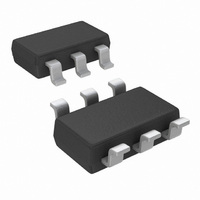
... The DAC121S101 is available in a 6-lead TSOT and an 8-lead MSOP and the DAC121S101Q is avail- able in the 6-lead TSOT only. Pin Configuration SPI ™ trademark of Motorola, Inc. © 2010 National Semiconductor Corporation DAC121S101/DAC121S101Q Features ■ DAC121S101Q is AEC-Q100 Grade 1 qualified and is manufactured on an Automotive Grade Flow. ■ ...
Page 2
Ordering Information Order Numbers DAC121S101CIMM DAC121S101CIMMX DAC121S101CIMK DAC121S101CIMKX DAC121S101QCMK DAC121S101QCMKX DAC121S101EVAL Block Diagram Pin Descriptions TSOT MSOP (SOT-23) Symbol Pin No. Pin No OUT 2 8 GND ...
Page 3
... Absolute Maximum Ratings 2) If Military/Aerospace specified devices are required, please contact the National Semiconductor Sales Office/ Distributors for availability and specifications. Supply Voltage Voltage on any Input Pin Input Current at Any Pin (Note 3) Package Input Current (Note 3) Power Consumption 25°C A ESD Susceptibility ...
Page 4
Symbol Parameter I Output Short Circuit Current OS LOGIC INPUT I Input Current (Note 10 Input Low Voltage (Note IL V Input High Voltage (Note IH C Input Capacitance (Note IN POWER REQUIREMENTS I Supply Current (output unloaded) ...
Page 5
A.C. and Timing Characteristics The following specifications apply for V range 48 to 4047. Boldface limits apply for T Symbol Parameter f SCLK Frequency SCLK Output Voltage Settling Time t s (Note 10) SR Output Slew Rate Glitch Impulse Digital ...
Page 6
... Obviously, such conditions should always be avoided. Note 5: Human body model is 100 pF capacitor discharged through a 1.5 kΩ resistor. Machine model is 220 pF discharged through ZERO Ohms. Note 6: See the section entitled "Surface Mount" found in any post 1986 National Semiconductor Linear Data Book for methods of soldering surface mount devices. ...
Page 7
Transfer Characteristic FIGURE 1. Input / Output Transfer Characteristic Timing Diagram FIGURE 2. DAC121S101 Timing 7 20114905 20114906 www.national.com ...
Page 8
Typical Performance Characteristics otherwise stated DNL 3.0V A INL 3.0V A TUE 3.0V A www.national.com MHz 25C, Input Code Range 48 to 4047, unless SCLK A ...
Page 9
DNL vs 20114922 3V DNL vs. f SCLK 20114950 3V DNL vs. Clock Duty Cycle 20114924 INL vs DNL vs. f SCLK 5V DNL vs. Clock Duty Cycle 9 20114923 20114951 20114925 www.national.com ...
Page 10
DNL vs. Temperature 3V INL vs INL vs. Clock Duty Cycle www.national.com 20114926 SCLK 20114928 20114930 10 5V DNL vs. Temperature 20114927 5V INL vs. f SCLK 20114929 5V INL vs. Clock Duty Cycle 20114931 ...
Page 11
INL vs. Temperature 20114932 Zero Code Error vs. f SCLK 20114934 Zero Code Error vs. Temperature 20114936 5V INL vs. Temperature Zero Code Error vs. Clock Duty Cycle Full-Scale Error vs 20114933 20114935 SCLK 20114937 www.national.com ...
Page 12
Full-Scale Error vs. Clock Duty Cycle Supply Current vs Glitch Response www.national.com Full-Scale Error vs. Temperature 20114938 Supply Current vs. Temperature A 20114944 20114946 12 20114939 20114945 Power-On Reset 20114947 ...
Page 13
Wake-Up Time 20114948 5V Wake-Up Time 13 20114949 www.national.com ...
Page 14
Functional Description 1.1 DAC SECTION The DAC121S101 is fabricated on a CMOS process with an architecture that consists of switches and a resistor string that are followed by an output buffer. The power supply serves as the reference voltage. ...
Page 15
POWER-ON RESET The power-on reset circuit controls the output voltage during power-up. Upon application of power the DAC register is filled with zeros and the output voltage is 0 Volts and remains there until a valid write sequence is ...
Page 16
Microwire Interface Figure 8 shows an interface between a Microwire compatible device and the DAC121S101. Data is clocked out on the rising edges of the SCLK signal. FIGURE 8. Microwire Interface 2.2 USING REFERENCES AS POWER SUPPLIES Recall the ...
Page 17
FIGURE 11. Using the LP3985 regulator Like any low dropout regulator, the LP2980 requires an output capacitor for loop stability. This output capacitor must be at least 1.0µF over temperature, but values of 2.2µF or more will provide even better ...
Page 18
The output voltage of this circuit for any code is found 4096) x ((R1 + R2 where D is the input code in decimal form. With ...
Page 19
Physical Dimensions inches (millimeters) unless otherwise noted Order Numbers DAC121S101CIMK and DAC121S101QCMK 8-Lead MSOP Order Number DAC121S101CIMM NS Package Number MUA08A 6-Lead TSOT NS Package Number MK06A 19 www.national.com ...
Page 20
... For more National Semiconductor product information and proven design tools, visit the following Web sites at: www.national.com Products Amplifiers www.national.com/amplifiers Audio www.national.com/audio Clock and Timing www.national.com/timing Data Converters www.national.com/adc Interface www.national.com/interface LVDS www.national.com/lvds Power Management www.national.com/power Switching Regulators www.national.com/switchers LDOs www.national.com/ldo LED Lighting www ...