5748536-1 TE Connectivity, 5748536-1 Datasheet - Page 3
5748536-1
Manufacturer Part Number
5748536-1
Description
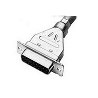
D SUB SHELL, RECEPTACLE, SIZE 1, STEEL
Manufacturer
TE Connectivity
Series
AMPLIMITE HDP-20r
Specifications of 5748536-1
Connector Type
D Sub
Connector Shell Size
1
Connector Body Material
Metal
No. Of Contacts
9
Contact Termination
Crimp
Rohs Compliant
Yes
Product Type
Connector
Product Series
HDP-20 (Crimp Snap)
Mating Connector Lock
With
Mating Connector Lock Type
Clinch Nut, 4-40 UNC
Shell Size
1
Shell Type
Full Metal Shell
Grounding Indents
Without
Grade
Standard
Color
Black
Shell Material
Steel
Shield Material
Steel
Shielded
Yes
Number Of Positions
9
Pre-assembled
No
Cable Insulation Diameter (mm [in])
4.19 – 11.56 [0.165 – 0.455]
Shell Plating
Tin over Copper
Shield Plating
Tin
Insert Material
Thermoplastic
Insert Flammability Rating
UL 94V-0
Cable Diameter (max.) (mm [in])
8.89 [0.350]
Preloaded
No
Contact Size
20
Enclosure
With
Connector Style
Receptacle
Housing Material
Nylon
Ul Flammability Rating
UL 94V-0
Housing Color
Black
Rohs/elv Compliance
RoHS compliant, ELV compliant
Lead Free Solder Processes
Not relevant for lead free process
Rohs/elv Compliance History
Always was RoHS compliant
Packaging Method
Bulk
Packaging Quantity
100
For Use With
HDP-20 Series D Sub Connectors
Available stocks
Company
Part Number
Manufacturer
Quantity
Price
Company:

Part Number:
5748536-1
Manufacturer:
TE
Quantity:
20 000


Tem perature rise vs current.
Vibration, random .
Mechanical shock.
Durability.
Mating force.
Unm ating force.
Contact insertion force.
Rev F
Test Description
30°C m axim um tem perature rise at
specified current.
No discontinuities of 1 m icrosecond
or longer duration.
See Note.
No discontinuities of 1 m icrosecond
or longer duration.
See Note.
See Note.
Size Posn
Size Posn
13.3 N [3 lbf] m axim um per contact. EIA-364-5.
1
2
3
4
5
1
2
3
4
5
15
25
37
50
15
25
37
50
9
9
Figure 1 (continued)
MECHANICAL
Requirem ent
12.5 [2.8]
20.9 [4.7]
34.7 [7.8]
51.6 [11.6] 177.9 [40]
69.4 [15.6] 195.7 [44]
12.5 [2.8]
20.9 [4.7]
34.7 [7.8]
51.6 [11.6] 177.9 [40]
69.4 [15.6] 195.7 [44]
(N [lbf] m axim um )
W ithout
(N [lbf] m axim um )
W ithout
Ground Indents
Ground Indents
133.4 [30]
146.8 [33]
164.6 [37]
133.4 [30]
146.8 [33]
164.6 [37]
W ith
W ith
EIA-364-70, Method 1.
Stabilize at a single current level
until 3 readings at 5 m inute intervals
are within 1°C.
See Figure 4.
EIA-364-28, Test Condition V,
Condition F.
Subject m ated specim ens to 20.71
G's rm s between 50 to 2000 Hz.
Fifteen m inutes in each of 3
m utually perpendicular planes.
See Figure 5.
EIA-364-27, Method A.
Subject m ated specim ens to 50 G's
half-sine shock pulses of 11
m illiseconds duration. Three shocks
in each direction applied along 3
m utually perpendicular planes, 18
total shocks.
See Figure 5.
EIA-364-9.
Mate and unm ate gold flash
specim ens for 100 cycles, and 30
ìin gold specim ens for 500 cycles
at a m axim um rate of 200 cycles
per hour.
EIA-364-13.
Measure force necessary to m ate
specim ens at a m axim um rate of
25.4 m m [1 in] per m inute.
EIA-364-13.
Measure force necessary to unm ate
specim ens at a m axim um rate of
25.4 m m [1 in] per m inute.
Measure force necessary to insert
contact into housing.
Procedure
108-40005
3 of 10
Related parts for 5748536-1
Image
Part Number
Description
Manufacturer
Datasheet
Request
R

Part Number:
Description:
Printers THERMAL PRINTER HS-SLEEVE MARKER
Manufacturer:
TE Connectivity


Part Number:
Description:
High Speed / Modular Connectors 30P HEADER ASSY
Manufacturer:
TE Connectivity
Datasheet:

Part Number:
Description:
High Speed / Modular Connectors REC 6X005P R/A LT B-PLANE HS3
Manufacturer:
TE Connectivity
Datasheet:

Part Number:
Description:
High Speed / Modular Connectors 2MM HM RCPT 50P R/A AU
Manufacturer:
TE Connectivity
Datasheet:

Part Number:
Description:
High Speed / Modular Connectors 2MM HM RCPT 50P R/A AU
Manufacturer:
TE Connectivity
Datasheet:


Part Number:
Description:
Manufacturer:
TE Connectivity
Datasheet:


Part Number:
Description:
Manufacturer:
TE Connectivity
Datasheet:

Part Number:
Description:
Manufacturer:
TE Connectivity
Datasheet:

Part Number:
Description:
Manufacturer:
TE Connectivity
Datasheet: