5749246-1 TE Connectivity, 5749246-1 Datasheet - Page 2
5749246-1
Manufacturer Part Number
5749246-1
Description
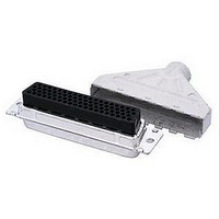
D SUB SHELL, RECEPTACLE, SIZE 2, STEEL
Manufacturer
TE Connectivity
Series
AMPLIMITE HDP-20r
Specifications of 5749246-1
Connector Type
D Sub
Connector Shell Size
2
Connector Body Material
Metal
Body Material
Steel
No. Of Contacts
15
Rohs Compliant
Yes
Product Type
Connector
Product Series
HDP-20 (Crimp Snap)
Mating Connector Lock
With
Mating Connector Lock Type
Slide Latches
Shell Size
2
Shell Type
Full Metal Shell
Grounding Indents
Without
Grade
Standard
Enclosure Material
PVC, Elastomer, Styrene polyolefin
Color
Black
Shell Material
Carbon Steel
Shield Material
Steel
Shielded
Yes
Number Of Positions
15
Pre-assembled
Yes
Cable Insulation Diameter (mm [in])
4.83 – 9.53 [0.190 – 0.375]
Shell Plating
Tin over Copper
Shield Plating
Tin over Copper
Insert Material
Nylon
Insert Flammability Rating
UL 94V-0
Locking Post Material
Brass
Locking Post Plating
Tin over matte Copper
Preloaded
No
Contact Size
20
Enclosure
With
Connector Style
Receptacle
Housing Material
Nylon
Ul Flammability Rating
UL 94V-0
Housing Color
Black
Rohs/elv Compliance
RoHS compliant, ELV compliant
Lead Free Solder Processes
Not relevant for lead free process
Rohs/elv Compliance History
Always was RoHS compliant
For Use With
HDP-20 Series D Sub Connectors


3.2.
3.3.
3.4.
3.5.
Exam ination of product.
Final exam ination of product.
Low level contact resistance.
Contact resistance, specified
current.
Insulation resistance.
W ithstanding voltage.
Rev F
Material
Materials used in the construction of this product shall be as specified on the applicable product
drawing.
Ratings
!
!
!
Perform ance and Test Description
Product is designed to m eet the electrical, m echanical and environm ental perform ance requirem ents
specified in Figure 1. Unless otherwise specified, all tests are perform ed at am bient tem perature.
Test Requirem ents and Procedures Sum m ary
Test Description
Voltage: 250 volts AC
Current: Fully loaded and energized connectors, see Figure 4
•
•
•
Tem perature: -55 to 105°C
18 AW G: 3.1 am peres
22 AW G: 2.0 am peres
28 AW G: 1.2 am peres
Meets visual requirem ents.
15 m illiohm s m axim um .
Meets requirem ents of product
drawing and Application
Specification 114-40030.
5000 m egohm s m inim um initial.
500 m egohm s m inim um final.
One m inute hold with no breakdown
or flashover. 0.5 m illiam pere
m axim um leakage current.
(AW G) (am peres)
W ire
Size
18
20
22
24
26
28
Figure 1 (continued)
ELECTRICAL
Current
Requirem ent
Test
3.1
2.4
2.0
1.6
1.3
1.2
Resistance
(m illiohm s)
Maxim um
15
15
15
15
15
15
EIA-364-18.
EIA-364-23.
EIA-364-18.
Visual and dim ensional (C of C)
inspection per product drawing.
Visual inspection.
Subject specim ens to 100
m illiam peres m axim um and 20
m illivolts m axim um open circuit
voltage.
See Figure 3.
EIA-364-6.
Measure potential drop of m ated
contacts assem bled in housing.
Calculate resistance.
See Figure 3.
EIA-364-21.
Test between adjacent contacts of
unm ated specim ens.
EIA-364-20, Condition I.
1000 volts AC at sea level.
Test between adjacent contacts of
unm ated specim ens.
Procedure
108-40005
2 of 10
Related parts for 5749246-1
Image
Part Number
Description
Manufacturer
Datasheet
Request
R

Part Number:
Description:
Printers THERMAL PRINTER HS-SLEEVE MARKER
Manufacturer:
TE Connectivity


Part Number:
Description:
High Speed / Modular Connectors 30P HEADER ASSY
Manufacturer:
TE Connectivity
Datasheet:

Part Number:
Description:
High Speed / Modular Connectors REC 6X005P R/A LT B-PLANE HS3
Manufacturer:
TE Connectivity
Datasheet:

Part Number:
Description:
High Speed / Modular Connectors 2MM HM RCPT 50P R/A AU
Manufacturer:
TE Connectivity
Datasheet:

Part Number:
Description:
High Speed / Modular Connectors 2MM HM RCPT 50P R/A AU
Manufacturer:
TE Connectivity
Datasheet:


Part Number:
Description:
Manufacturer:
TE Connectivity
Datasheet:


Part Number:
Description:
Manufacturer:
TE Connectivity
Datasheet:

Part Number:
Description:
Manufacturer:
TE Connectivity
Datasheet:

Part Number:
Description:
Manufacturer:
TE Connectivity
Datasheet: