5747144-2 TE Connectivity, 5747144-2 Datasheet - Page 3
5747144-2
Manufacturer Part Number
5747144-2
Description
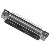
D SUB CONNECTOR, STANDARD, 50POS, RCPT
Manufacturer
TE Connectivity
Series
AMPLIMITE HD-20r
Specifications of 5747144-2
Connector Type
D Sub
No. Of Contacts
50
D Sub Shell Size
DD
Connector Body Material
Metal
Gender
Receptacle
Contact Termination
Through Hole
Rohs Compliant
Yes
Number Of Positions / Contacts
50
Contact Plating
Gold Flash over Palladium Nickel, Gold (30) over Nickel
Shell Plating
Tin
Shell Size
5
Mounting Style
Through Hole
Mounting Angle
Vertical
Contact Material
Copper Alloy
Flammability Rating
UL 94 V-0
Housing Material
Thermoplastic, Glass Filled
Pcb Mounting Orientation
Vertical
Product Series
HD 20
Mating Connector Lock
With
Mating Connector Lock Type
Threaded Insert, 4-40 UNC
Pcb Mount Retention
With
Shell Type
Front Metal Shell
Grounding Indents
Without
Grounding Straps
Without
Pcb Mount Style
Through Hole
Color Code
None
Sealed
No
Profile
Standard
Mounting Hole Diameter (mm [in])
3.05 [.120]
Shell Material
Steel
Threaded Insert Material
Brass
Panel Mount Retention
Without
Grounding Clips
Without
Termination Post Length (mm [in])
5.80 [0.228]
Solder Tail Contact Plating
Tin over Nickel
Number Of Positions
50
Pcb Mount Retention Type
Compliant Posts, Mounting Holes
Contact Plating, Mating Area, Material
Gold Flash over Palladium Nickel or Gold (30) over Nickel
Contact Base Material
Copper Alloy
Connector Style
Receptacle
Ul Flammability Rating
UL 94V-0
Rohs/elv Compliance
RoHS compliant, ELV compliant
Lead Free Solder Processes
Not relevant for lead free process
Rohs/elv Compliance History
Always was RoHS compliant
Pcb Thickness, Recommended (in [mm])
0.093 [2.36]
Application
Standard
Lead Free Status / Rohs Status
Details
Available stocks
Company
Part Number
Manufacturer
Quantity
Price
Company:

Part Number:
5747144-2
Manufacturer:
TE Connectivity AMP Connectors
Quantity:
5 696


Rev B
Contact retention.
Mating force.
Unm ating force.
Therm al shock.
Hum idity-tem perature cycling.
Tem perature life.
Mixed flowing gas.
NOTE
Test Description
Shall meet visual requirements, show no physical damage and shall meet requirements of
additional tests as specified in Test Sequence in Figure 2.
Contacts shall not dislodge.
Connector
Connector
See Note.
See Note.
See Note.
See Note.
Position
Position
15
25
37
50
15
25
37
50
9
9
ENVIRONMENTAL
Figure 1 (end)
Requirem ent
w/Grounding Indents
w/Grounding Indents
Lbs Maxim um
Lbs Maxim um
15
20
30
40
50
15
20
30
40
50
TE Spec 109-30.
Apply axial load of 5 pounds at a
rate of 1 pound per second and
m aintain for 5 seconds to each
contact in direction opposite of
insertion.
TE Spec 109-42, Condition A.
Measure force necessary to m ate
sam ples at a m axim um rate of 1
inch per m inute.
TE Spec 109-42, Condition A.
Measure force necessary to
unm ate sam ples at a m axim um
rate of 1 inch per m inute.
TE Spec 109-22.
Subject m ated sam ples to 5 cycles
between -55 and 105°C.
TE Spec 109-23-3, Condition B.
Subject m ated sam ples to 10
cycles between 25 and 65°C at
95% RH.
TE Spec 109-43.
Subject m ated sam ples to
tem perature life at 105°C for 500
hours.
TE Spec 109-85-2.
Subject m ated sam ples to
environm ental class II for 14 days.
Procedure
108-40014
3 of 6
Related parts for 5747144-2
Image
Part Number
Description
Manufacturer
Datasheet
Request
R

Part Number:
Description:
Printers THERMAL PRINTER HS-SLEEVE MARKER
Manufacturer:
TE Connectivity


Part Number:
Description:
High Speed / Modular Connectors 30P HEADER ASSY
Manufacturer:
TE Connectivity
Datasheet:

Part Number:
Description:
High Speed / Modular Connectors REC 6X005P R/A LT B-PLANE HS3
Manufacturer:
TE Connectivity
Datasheet:

Part Number:
Description:
High Speed / Modular Connectors 2MM HM RCPT 50P R/A AU
Manufacturer:
TE Connectivity
Datasheet:

Part Number:
Description:
High Speed / Modular Connectors 2MM HM RCPT 50P R/A AU
Manufacturer:
TE Connectivity
Datasheet:


Part Number:
Description:
Manufacturer:
TE Connectivity
Datasheet:


Part Number:
Description:
Manufacturer:
TE Connectivity
Datasheet:

Part Number:
Description:
Manufacturer:
TE Connectivity
Datasheet:

Part Number:
Description:
Manufacturer:
TE Connectivity
Datasheet: