1-173977-2 TE Connectivity, 1-173977-2 Datasheet
1-173977-2
Specifications of 1-173977-2
Available stocks


Related parts for 1-173977-2


1-173977-2 Summary of contents
Page 1
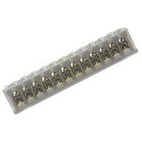
... Scope: 1.1 Contents: This specification covers the requirements for product performance, test methods and quality assurance provisions of AMP Common Termination (CT), Connector, 2mm Pitch, M/T Type. The applicable product description and part numbers are as shown in Fig.1: Product Part No. X-173977-X X-179694-X 2. Applicable Documents: The following documents form a part of this specification to the extent specified herein ...
Page 2
... Pretinned Brass (0.8um min. thick solder-plated over 0.5um min. thick copper underplate) : 6/6 Nylon (UL94 V-0) : Brass (0.2um min. thick Au Plated over 1~2um thick Nickel underplate) : 6/6 Nylon GF Type (UL94 V-0) : Pretin lead Brass (0.8um min. thick solder-plated over 0.5um min. ...
Page 3
... A. Board Thickness B. Hole Diameter 3.6 Applicable Panel Thickness: 0.8~1.6mm (To be used for post header and relay) 3.7 Performance Requirements and Test Descriptions: The product shall be designed to meet the electrical, mechanical and environmental performance requirements specified in Fig.2, Para. 3.8. All tests shall be performed at ambient temperature unless otherwise specified ...
Page 4
... Fig. 2 (To be continued) PAGE Document No Procedures Subject terminated connector and header to mate and unmate to measure the force required to engage and disengage by operating the head at a rate minute. Record by using autograph. Lock Side. 7.84 9.80 12.74 16 ...
Page 5
... Apply a pull-off load to Axial terminated wire of contact secured on the tester rate [Min.] of 100mm a minute. The load is applied in the axial and lateral directions as specified. 14.7 19.6 19.6 Axial 14.7 19 ...
Page 6
... Product shall be confirming to the requirements of applicable product drawing and Application Specification 114-5104. Electrical Performance Requirements 10 m Max. (Initial Max. (Final) Connector must withstand test potential of 1.0 kV (AC) for 1 minute. Current leakage must be 5.0mA Max. 1000 M Min. (Initial max. under loaded specified current. See Fig. 3. ...
Page 7
... Resistance (low level) (Final) must meet visual & electrical requirements, which applicable. Fig. 2 (To be continued) PAGE Document No Procedures Subject mated connectors to 10-55 traversed in 1 minute at 1.52 mm amplitude 2 hours each of 3 mutually perpendicular planes. MIL-STD-202, Method 201, Condition A. Subject mated connectors to 490.3 2 m/s halfsine shock pulses of 11milisecond duration ...
Page 8
... SMT product mounted on printed circuit boards to solder reflow as like Fig. 7. See Para. 3.8.3 (11-1) and Para. 3.8.3 (11-2) Subject connector assembly to 30 cycles of repeated mating/unmating at a rate of 10 cycles a minute. Subject mated connector to temperature changes between and 65 C with 95 % R.H. ...
Page 9
... Fig.5 Tyco Electronics AMP Shanghai Ltd. ASHL-0005- ES REV B Fig.3 Fig.4 Fig.6 Fig.7 PAGE Document No 108-5218 REV LOC S ES ...
Page 10
... Test Specimens: The test specimens to be used for the performance evaluation testing, shall be prepared in accordance with AMP Application Specification, 114-5104, Termination of AMP CT Connector Pitch, M/T Type, by using the samples selected from the current production at random, and conforming to the requirements of the applicable product drawing. ...
Page 11
... The applicable product descriptions and part numbers are as shown in Appendix 1. Product Part No. Product Descriptions X-173979-X Post Header, Horizontal (H) X-176931-X Post Header, Horizontal (H), in Tube X-176303-X Post Header, Horizontal (H), w/o Kink X-176304-X Post Header, Horizontal (H), w/o Kink, in Tube X-173981-X Post Header, Vertical (V) ...
Page 12
... Pos. 6 Pos. 2~9 Pos. 2~9 Pos. 2~9 Pos. 2~9 Pos. 3 Pos. 3 Pos. 2~6, 8 Pos. 2~6, 8 Pos. 2~5 Pos. 2~5 Pos. 2~6, 8 Pos 8~11 Pos. 3 Pos. 7~10, 13 Pos. 2~8 Pos. 2~8 Pos. 2 Pos. 3 Pos. 3 Pos. 2~8 Pos. 2~8 Pos. REV LOC S ...