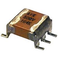
87106-013 AVX Corporation, 87106-013 Datasheet - Page 19

87106-013
Manufacturer Part Number
87106-013
Description
CAPACITOR CERAMIC, 3.3UF, 50V, X7R, DIP
Manufacturer
AVX Corporation
Datasheet
1.SM049C225KBN290.pdf
(21 pages)
Specifications of 87106-013
Dielectric Characteristic
X7R
Capacitance
3.3µF
Capacitance Tolerance
± 10%
Voltage Rating
50VDC
Capacitor Case Style
DIP
No. Of Pins
6
Capacitor Mounting
Through Hole
Rohs Compliant
No
SMPS Stacked MLC Capacitors
(SM9 Style) Technical Information on SMPS Capacitors
ELECTRICAL SPECIFICATIONS
Temperature Coefficient
C0G: A Temperature Coefficient - 0 ±30 ppm/°C, -55° to +125°C
X7R: C Temperature Coefficient - ±15%, -55° to +125°C
Z5U: E Temperature Coefficient - +22, -56%, +10° to +85°C
Capacitance Test (MIL-STD-202 Method 305)
C0G: 25°C, 1.0±0.2 Vrms (open circuit voltage) at 1KHz
X7R: 25°C, 1.0±0.2 Vrms (open circuit voltage) at 1KHz
Z5U: 25°C, 0.5 Vrms max (open circuit voltage) at 1KHz
Dissipation Factor 25°C
C0G: 0.15% Max @ 25°C, 1.0±0.2 Vrms (open circuit voltage) at 1KHz
X7R: 2.5% Max @ 25°C, 1.0±0.2 Vrms (open circuit voltage) at 1KHz
Z5U: 3.0% Max @ 25°C, 0.5 Vrms max (open circuit voltage) at 1KHz
Insulation Resistance 25°C (MIL-STD-202 Method 302)
C0G and X7R: 100K MΩ or 1000 MΩ-μF, whichever is less.
Z5U: 10K MΩ or 1000 MΩ-μF, whichever is less.
Insulation Resistance 125°C (MIL-STD-202 Method 302)
C0G and X7R: 10K MΩ or 100 MΩ-μF, whichever is less.
Z5U: 1K MΩ or 100 MΩ-μF, whichever is less.
HOW TO ORDER
Note: Capacitors with X7R and Z5U dielectrics are not intended for applications
26
Size
SM9 = Plastic
AVX Style
across AC supply mains or AC line filtering with polarity reversal. Contact plant
for recommendations.
SM9
Case
dimen-
chart
See
sions
Size
1
500V = 7
Voltage
100V = 1
200V = 2
50V = 5
7
Temperature
Coefficient
C0G = A
X7R = C
Z5U = E
C
ESR @ 10KHz
ESR @ 50KHz
ESR @ 100KHz
ESR @ 500KHz
ESR @ 1MHz
ESR @ 5MHz
ESR @ 10MHz
220,000 pF = 224
22,000 pF = 223
1,000 pF = 102
100 pF = 101
100 μF = 107
Capacitance
10 pF = 100
(2 significant C0G: J = ±5%
10 μF = 106
AVX Styles: SM91, SM92, SM93, SM94, SM95, SM96
digits + no.
1 μF = 105
of zeros)
106
Code
Typical ESR Performance (mΩ)
Electrolytic
100μF/50V
Aluminum
300
285
280
265
265
335
560
Dielectric Withstanding Voltage 25°C (Flash Test)
C0G and X7R: 250% rated voltage for 5 seconds with 50 mA max
Z5U: 200% rated voltage for 5 seconds with 50 mA max charging
Life Test (1000 hrs)
C0G and X7R: 200% rated voltage at +125°C. (500 Volt units @
Z5U: 150% rated voltage at +85°C
Moisture Resistance (MIL-STD-202 Method 106)
C0G, X7R, Z5U: Ten cycles with no voltage applied.
Thermal Shock (MIL-STD-202 Method 107, Condition A)
Immersion Cycling (MIL-STD-202 Method 104, Condition B)
Resistance To Solder Heat (MIL-STD-202, Method 210,
*
X7R: K = ±10%
Z5U: Z = +80, -20%
Hi-Rel screening for C0G and X7R only. Screening consists of 100% Group A
(B Level), Subgroup 1 per MIL-PRF-49470.
Capacitance
charging current. (500 Volt units @ 750 VDC)
600 VDC)
Condition B, for 20 seconds)
current.
Tolerance
M = ±20%
M = ±20%
K = ±10%
P = GMV (+100, -0%)
Z = +80, -20%
M
Solid Tantalum
100μF/10V
Low ESR
72
67
62
56
56
72
91
B = Hi-Rel
A = Standard
Level
Test
A
Solid Aluminum
Electrolytic
100μF/16V
*
29
22
20
18
17
17
22
Termination
N = Straight Lead
J = Leads formed
L = Leads formed
in
out
N
100μF/50V
MLCC
SMPS
12.5
2.5
20
3
2
4
7
page 28 for
4.7μF/50V
See table
Height
max cap.
MLCC
660
SMPS
height
7.5
per
66
23
15
14
on
8
8


