M49470X01126KAN AVX Corporation, M49470X01126KAN Datasheet - Page 6
M49470X01126KAN
Manufacturer Part Number
M49470X01126KAN
Description
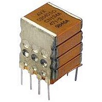
CAPACITOR CERAMIC, 12UF, 50V, X7R, DIP
Manufacturer
AVX Corporation
Datasheet
1.SM049C225KBN290.pdf
(21 pages)
Specifications of M49470X01126KAN
Dielectric Characteristic
X7R
Capacitance
12µF
Capacitance Tolerance
± 10%
Voltage Rating
50VDC
Capacitor Case Style
DIP
No. Of Pins
8
Capacitor Mounting
Through Hole
Lead Spacing
10.2mm
Rohs Compliant
No


SMPS Stacked MLC Capacitors
(SM Style) SM Military Styles MIL-PRF-49470/2
MIL-PRF-49470/2
MIL-PRF-49470/2 - capacitor, fixed, ceramic dielectric, switch mode power supply (general purpose and temperature stable),
standard reliability and high reliability encapsulated, Style PS02.
DIMENSIONS:
NOTES:
1. Dimensions are in millimeters (inches)
2. Unless otherwise specified, tolerances are 0.254 (±0.001).
3. See table I of MIL-PRF-49470/2 for specific maximum A dimension. For
4. Lead alignment within pin rows shall be within ±0.10 (0.004).
SEATING
PLANE
4.45 (0.175) MAX
1.02 (0.040) MIN
all lead styles, the number of chips is determined by the capacitance and
voltage rating.
Case Code
L
LEAD STYLE J AND C
1
2
3
4
5
6
See Note 3
A MAX
C
E
C ±0.635 (±0.025)
1.27 (0.050) MIN
11.4 (0.450)
20.3 (0.800)
11.4 (0.450)
10.2 (0.400)
6.35 (0.250)
31.8 (1.250)
D
0.254 (0.010)
RAD (TYP)
2.54 (0.100) TYP
(0.020 ±0.002)
0.50 ±0.05
(0.015 ±0.005)
D ±0.635 (±0.025)
0.38 ±0.13
See Note 4
54.7 (2.155)
41.0 (1.615)
29.3 (1.155)
12.3 (0.485)
9.02 (0.355)
54.7 (2.155)
CIRCUIT DIAGRAM
14.7 (0.580)
24.1 (0.950)
14.7 (0.580)
12.3 (0.485)
9.02 (0.355)
36.3 (1.430)
E (max)
(0.010 ±0.002)
0.254 ±0.05
LEAD STYLE N AND A
LEAD STYLE L AND B
millimeters (inches)
L
Number of Leads
per side
20
15
10
20
C
E
4
3
C
E
6.35 (0.250)
MIN
1.27 (0.050) MIN
0.254 (0.010)
RAD (TYP)
13
Related parts for M49470X01126KAN
Image
Part Number
Description
Manufacturer
Datasheet
Request
R

Part Number:
Description:
Manufacturer:
AVX Corporation
Datasheet:
Part Number:
Description:
Manufacturer:
AVX Corporation
Datasheet:
Part Number:
Description:
Manufacturer:
AVX Corporation
Datasheet:
Part Number:
Description:
Manufacturer:
AVX Corporation
Datasheet:
Part Number:
Description:
Manufacturer:
AVX Corporation
Datasheet: