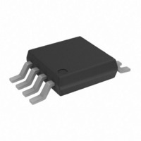
AD7303BRM Analog Devices Inc, AD7303BRM Datasheet - Page 9

AD7303BRM
Manufacturer Part Number
AD7303BRM
Description
IC DAC 8BIT DUAL R-R 8-MSOP
Manufacturer
Analog Devices Inc
Datasheet
1.AD7303BRZ.pdf
(16 pages)
Specifications of AD7303BRM
Rohs Status
RoHS non-compliant
Settling Time
1.2µs
Number Of Bits
8
Data Interface
Serial
Number Of Converters
2
Voltage Supply Source
Single Supply
Power Dissipation (max)
6.93mW
Operating Temperature
-40°C ~ 105°C
Mounting Type
Surface Mount
Package / Case
8-MSOP, Micro8™, 8-uMAX, 8-uSOP,
Available stocks
Company
Part Number
Manufacturer
Quantity
Price
Company:
Part Number:
AD7303BRM
Manufacturer:
AD
Quantity:
5 321
Company:
Part Number:
AD7303BRM
Manufacturer:
AD
Quantity:
13 888
Company:
Part Number:
AD7303BRM
Manufacturer:
AD
Quantity:
4 130
Part Number:
AD7303BRM
Manufacturer:
ADI/亚德诺
Quantity:
20 000
Part Number:
AD7303BRM-REEL7
Manufacturer:
ADI/亚德诺
Quantity:
20 000
Company:
Part Number:
AD7303BRMREEL7
Manufacturer:
NXP
Quantity:
5 869
Company:
Part Number:
AD7303BRMZ
Manufacturer:
OKI
Quantity:
6 220
Part Number:
AD7303BRMZ
Manufacturer:
ADI/亚德诺
Quantity:
20 000
REV. 0
SERIAL INTERFACE
The AD7303 contains a versatile 3-wire serial interface that is
compatible with SPI, QSPI and Microwire interface stan-
dards as well as a host of digital signal processors. An active
low SYNC enables the shift register to receive data from the
serial data input DIN. Data is clocked into the shift register on
the rising edge of the serial clock. The serial clock frequency
can be as high as 30 MHz. This shift register is 16 bits wide as
shown in Figures 23 and 24. The first eight bits are control bits
and the second eight bits are data bits for the DACs. Each
transfer must consist of a 16-bit transfer. Data is sent MSB first
and can be transmitted in one 16-bit write or two 8-bit writes.
SPI and Microwire interfaces output data in 8-bit bytes and
thus require two 8-bit transfers. In this case the SYNC input to
the DAC should remain low until all sixteen bits have been
transferred to the shift register. QSPI interfaces can be pro-
MSB
LSB
INT/EXT
LDAC
PDB
PDA
CR1
CR0
DB7
DB6
DB5
DB4
DB3
DB2
DB1
DB0
A/B
X
8
7
SYNC
8
8
Figure 23. Logic Interface on the AD7303
REGISTER
REGISTER
LATCH & CLK
SEQUENCER
CLOCK BUS
INPUT
INPUT
DRIVERS
LATCH
16
8
8
SYNC
SCLK
DIN
DECODER
DECODER
BANDGAP POWER-DOWN
8 TO 32
8 TO 32
DAC A POWER-DOWN
DAC B POWER-DOWN
–9–
REF
SELECTOR
grammed to transfer data in 16-bit words. After clocking all six-
teen bits to the shift register, the rising edge of SYNC executes
the programmed function. The DACs are double buffered
which allows their outputs to be simultaneously updated.
INPUT SHIFT REGISTER DESCRIPTION
The input shift register is 16 bits wide. The first eight bits con-
sist of control bits and the last eight bits are data bits. Figure 23
shows a block diagram of the logic interface on the AD7303
DAC. The seven bits in the control word are taken from the in-
put shift register to a latch sequencer that decodes this data and
provides output signals that control the data transfers to the in-
put and data registers of the selected DAC, as well as output
updating and various power-down features associated with the
control section. A description of all bits contained in the input
shift register is given below.
REFERENCE
30
30
CURRENT
SWITCH
INT
REGISTER
REGISTER
DAC
DAC
REF
RESISTOR
SWITCH
30
30
BANDGAP
BIAS GEN
DAC A
DAC B
DAC A BIAS
DAC B BIAS
V
V
OUT
OUT
A
B
AD7303


