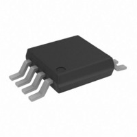
AD5452YRMZ Analog Devices Inc, AD5452YRMZ Datasheet - Page 25

AD5452YRMZ
Manufacturer Part Number
AD5452YRMZ
Description
IC DAC 12BIT MULT 50MHZ 8-MSOP
Manufacturer
Analog Devices Inc
Specifications of AD5452YRMZ
Data Interface
Serial
Design Resources
Unipolar, Precision DC Digital-to-Analog Conversion using AD5450/1/2/3 8-14-Bit DACs (CN0052) Precision, Bipolar, Configuration for AD5450/1/2/3 8-14bit Multiplying DACs (CN0053) AC Signal Processing Using AD5450/1/2/3 Current Output DACs (CN0054) Programmable Gain Element Using AD5450/1/2/3 Current Output DAC Family (CN0055) Single Supply Low Noise LED Current Source Driver Using a Current Output DAC in the Reverse Mode (CN0139)
Settling Time
110ns
Number Of Bits
12
Number Of Converters
1
Voltage Supply Source
Single Supply
Power Dissipation (max)
55µW
Operating Temperature
-40°C ~ 125°C
Mounting Type
Surface Mount
Package / Case
8-MSOP, Micro8™, 8-uMAX, 8-uSOP,
Resolution (bits)
12bit
Sampling Rate
2.7MSPS
Input Channel Type
Serial
Supply Voltage Range - Analogue
2.5V To 5.5V
Supply Current
400nA
Digital Ic Case
RoHS Compliant
Lead Free Status / RoHS Status
Lead free / RoHS Compliant
Available stocks
Company
Part Number
Manufacturer
Quantity
Price
Company:
Part Number:
AD5452YRMZ
Manufacturer:
AD
Quantity:
309
Part Number:
AD5452YRMZ
Manufacturer:
ADI/亚德诺
Quantity:
20 000
EVALUATION BOARD FOR THE DAC
The evaluation board consists of an AD5450, AD5451, A
or AD5453 DAC and a current-to-voltage amplifier, such as
AD8065. Included on the evaluation board is a 10 V reference,
ADR01. An external reference can also be applied via an SMB
input.
The evaluation kit consists of a CD with PC software to control
the DAC. The software allows the user to write code to the device.
P1–19
P1–20
P1–21
P1–22
P1–23
P1–24
P1–25
P1–26
P1–27
P1–28
P1–29
P1–30
P1–3
P1–2
P1–4
SCLK
SDIN
SYNC
P2–3
P2–2
P2–1
P2–4
10kΩ
R1
V
DD
1
Figure 64. Schematic of AD5450/AD5451/A D5452/AD5453 Evaluation Board
C11
0.1µF
C13
0.1µF
C15
0.1µF
J3
J4
J5
+
+
+
SYNC
SCLK
SDIN
C12
10µF
C14
10µF
C16
10µF
6
5
4
V
V
DD
SS
SCLK
SDIN
SYNC
AGND
V
DD
AD5450/
AD5451/
AD5452/
AD545
D5452,
1
U1
an
10µF
Rev. E | Page 25 of 32
C3
3
V
I
OUT
V
GND
DD
V
R
REF
+
DD
FB
0.1µF
1
C4
3
1
8
7
2
POWER SUPPLIES FOR THE EVALUATION BOARD
The board requires ±12 V and +5 V supplies. The +12 V V
and −12 V V
is used to power the DAC (V
Both supplies are decoupled to their respective ground plane
with 10 μF tantalum and 0.1 μF ceramic capacitors.
3
5
V
C1
0.1µF
REF
V
TRIM
C6
1.8pF
IN
V
GND
+
V
DD
J2
REF
U2
2
1
C2
10µF
AD5450/AD5451/AD5452/AD5453
V
OUT
SS
are used to power the output amplifier; the +5 V
4
1
AD8065AR
U3
C5
0.1µF
2
3
V
V
LK1
SS
DD
4
7
V–
V+
DD1
0.1µF
0.1µF
10µF
10µF
+
C10
) and transceivers (V
C7
C7
C9
+
6
TP
V
OUT
J1
CC
).
DD


