AD7845BQ Analog Devices Inc, AD7845BQ Datasheet - Page 8
AD7845BQ
Manufacturer Part Number
AD7845BQ
Description
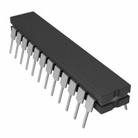
IC DAC 12BIT MULT LC2MOS 24-CDIP
Manufacturer
Analog Devices Inc
Datasheet
1.AD7845JNZ.pdf
(12 pages)
Specifications of AD7845BQ
Rohs Status
RoHS non-compliant
Settling Time
5µs
Number Of Bits
12
Data Interface
Parallel
Number Of Converters
1
Voltage Supply Source
Dual ±
Power Dissipation (max)
150mW
Operating Temperature
-40°C ~ 85°C
Mounting Type
Through Hole
Package / Case
24-CDIP (0.300", 7.62mm)
Available stocks
Company
Part Number
Manufacturer
Quantity
Price


AD7845
APPLI
PROGRAMMABLE GAIN AMPLIFIER (PGA)
The AD7845 performs a PGA function when connected as in
Figure 15. In this configuration, the R-2R ladder is connected
in the amplifier feedback loop. R
tor. As the code decreases, the R-2R ladder resistance increases
and so the gain increases.
As the programmed gain increases, the error and noise also
increase. For this reason, the maximum gain should be limited
to 256. Table III shows gain versus code.
Note that instead of using R
possible to use combinations of the other application resistors,
R
gain range for the same codes of Table II now goes from l/2
to 128.
Digital Inputs
1111
1000
0100
0010
0001
0000
0000
0000
0000
A
V
, R
OUT
Table III. Gain and Error vs. Input Code for Figure 15
= –V
B
CATION
and R
= –V
1111
0000
0000
0000
0000
1000
0100
0010
0001
IN
Figure 15. AD7845 Connected as PGA
IN
C
. For instance, if R
R
DAC
D
S CIRCUITS
R
DAC
D
1111
0000
0000
0000
0000
0000
0000
0000
0000
R
DAC
1
R
FB
1
FB
=
as the input resistor, it is also
Gain
4096/4095
2
4
8
16
32
64
128
256
, D
FB
B
–V
is used instead of R
is the amplifier input resis-
D
IN
0 to
, since R
4095
4096
1
FB
Error (%)
0.04
0.07
0.13
0.26
0.51
1.02
2.0
4.0
8.0
= R
FB
DAC
, the
–8–
PROGRAMMABLE CURRENT SOURCES
The AD7845 is ideal for designing programmable current
sources using a minimum of external components. Figures 16
and 17 are examples. The circuit of Figure 16 drives a program-
mable current I
Figure 17 shows the circuit for sinking a programmable current,
I
Note that by making R1 much smaller than R
becomes insensitive to both the absolute value of R
temperature variations. Now, the only resistor determining load
current I
If R1 = 100 , then the programming range is 0 mA to 100 mA,
and the resolution is 0.024 mA.
L
. The same set of circuit equations apply for both diagrams.
I
I
I
I
L
1
2
L
=
=
=
= I
=
D | V
D | V
R1
3
D | V
1
L
= I
Figure 16. Programmable Current Source
R
is the sense resistor R1.
R1
DAC
R1
2
+ I
IN
D | V
IN
IN
L
R
|
|
1
|
into a load referenced to a negative supply.
, D
DAC
+
IN
1
D | V
|
R
R
DAC
0 to
R
R1
DAC
FB
IN
4095
4096
=
|
D | V
R1
IN
|
, since R
DAC
, the circuit
DAC
FB
= R
and its
REV. B
DAC
Related parts for AD7845BQ
Image
Part Number
Description
Manufacturer
Datasheet
Request
R

Part Number:
Description:
±1.7g Dual-Axis IMEMS Accelerometer Evaluation Board
Manufacturer:
Analog Devices Inc
Datasheet:

Part Number:
Description:
Inertial Sensor Evaluation System
Manufacturer:
Analog Devices Inc
Datasheet:
Part Number:
Description:
Manufacturer:
Analog Devices Inc
Datasheet:
Part Number:
Description:
Manufacturer:
Analog Devices Inc
Datasheet:
Part Number:
Description:
Manufacturer:
Analog Devices Inc
Datasheet:
Part Number:
Description:
Manufacturer:
Analog Devices Inc
Datasheet:
Part Number:
Description:
Manufacturer:
Analog Devices Inc
Datasheet:
Part Number:
Description:
Manufacturer:
Analog Devices Inc
Datasheet:
Part Number:
Description:
Manufacturer:
Analog Devices Inc
Datasheet:
Part Number:
Description:
Manufacturer:
Analog Devices Inc
Datasheet:
Part Number:
Description:
Manufacturer:
Analog Devices Inc
Datasheet:
Part Number:
Description:
Manufacturer:
Analog Devices Inc
Datasheet:
Part Number:
Description:
Manufacturer:
Analog Devices Inc
Datasheet: