E2E-X2Y1-US Omron, E2E-X2Y1-US Datasheet - Page 15
E2E-X2Y1-US
Manufacturer Part Number
E2E-X2Y1-US
Description
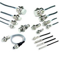
Proximity Sensors Proximity Sensor
Manufacturer
Omron
Series
E2Er
Type
Inductive Proximity Sensorr
Specifications of E2E-X2Y1-US
Proximity Sensor Type
Inductive
Proximity Sensor Sensing Distance
2mm
Proximity Sensor Sensing Distance Range
2 to 7mm
Proximity Sensor Switching Mode
NO
Ac Supply Voltage
20 to 264VAC
Mounting
Panel
Operating Temp Range
-40C to 85C
Operating Temperature Classification
Industrial
Pin Count
2
Maximum Operating Temperature
+ 85 C
Supply Voltage
30 V
Operating Supply Voltage
24 VAC to 240 VAC
Sensing Distance
2 mm
Minimum Operating Temperature
- 40 C
Maximum Output Current
200 mA
Features
High visibility indicator
Sensor Type
Inductive
Sensing Object
Metallic
Response Frequency
25Hz
Material - Body
Nickel-Plated Brass
Shielding
Shielded
Voltage - Supply
20 VAC ~ 264 VAC
Output Type
SCR-NO
Terminal Type
2-Wire
Package / Case
Cylinder, Threaded - M12
Lead Free Status / Rohs Status
Supplier Unconfirmed


J CONNECTING LOAD TO AC 2-WIRE
Refer to the following before using AC or DC 2-wire Proximity Sen-
sors.
Surge Protection
Although the Proximity Sensor has a surge absorption circuit, if
there is any machine that has a large surge current (e.g., a motor or
welding machine) near the Proximity Sensor, connect a surge ab-
sorber to the machine.
Leakage Current
When it is OFF, the Proximity Sensor has leakage current. Refer to
Leakage Current Characteristics. In this case, the load is imposed
with a small voltage and the load may not be reset. Before using the
Proximity Sensor, make sure that this voltage is less than the load
reset voltage. The AC 2-wire Proximity Sensor cannot be con-
nected to any card-lift-off relay (e.g., the G2A) because contact
vibration of the relay will be caused by the leakage current and the
life of the relay will be shortened.
Countermeasures Against Leakage Current
AC 2-wire Models
Connect a bleeder resistor as the bypass for the leakage current so
that the current flowing into the load will be less than the load reset
current.
J PRECAUTIONS FOR AC 2-WIRE PROXIMITY SENSORS IN OPERATION
Connector
E2E 2-WIRE AC
Model
AC
2-wire
SENSOR
Connection type
AND
(serial connection)
Method
Incorrect
Correct
Load
Load
Load
16
As shown in the following diagram, connect the bleeder resistor so
that the current flowing into the Proximity Sensor will be 10 mA mini-
mum and the residual voltage imposed on the load will be less than
the load reset voltage.
Refer to the following to calculate the bleeder resistance and the al-
lowable power of the bleeder resistor.
R ≦ V
P > V
P: The allowable power of the bleeder resistor. (The actual power
I:
The following resistors are recommended.
100 VAC (supply voltage): A resistor with a resistance of 10 kΩ max-
imum and an allowable power of 3 W minimum
200 VAC (supply voltage): A resistor with a resistance of 20 kΩ max-
imum and an allowable power of 10 W minimum
If these resistors generate excessive heat, use a resistor with a re-
sistance of 10 kΩ maximum and an allowable power of 5 W mini-
mum at 100 VAC and a resistor with a resistance of 20 kΩ maximum
and an allowable power of 10 W minimum at 200 VAC instead.
capacity of the bleeder resistor must be at least a few times as
large as the allowable power of the bleeder resistor.)
Load current (mA)
V
s
S
≧ 100 V
S
2
/(10 - - I) (kΩ)
/R (mW)
Description
If 100 or 200 VAC is imposed on the Proximity
Sensors, V
load) will be obtained from the following.
V
Sensors) (V)
Therefore, if V
voltage, the load will not operate.
A maximum of three Proximity Sensors can be
connected in series provided that the supply
voltage is 100 V minimum.
L
Bleeder resistor R
= V
S
Load
- - (residual voltage x no. of Proximity
L
(i.e., the voltage imposed on the
L
is lower than the load operating
VAC power
supply V
E2E 2-WIRE AC
S
Related parts for E2E-X2Y1-US
Image
Part Number
Description
Manufacturer
Datasheet
Request
R

Part Number:
Description:
E2E-X1C1 W/ ROBOTIC CABLE
Manufacturer:
Omron
Datasheet:
Part Number:
Description:
Proximity Sensors E2E-X5ME1 W/5M CABLE
Manufacturer:
Omron
Datasheet:
Part Number:
Description:
Proximity Sensors Prox Plug In
Manufacturer:
Omron
Datasheet:
Part Number:
Description:
Proximity Sensors PROX E2E-C1C1 W/ 5 M ETER CABLE
Manufacturer:
Omron
Datasheet:
Part Number:
Description:
Proximity Sensors E2E-X1C1 W/ SPECIAL ATTRIBUTES
Manufacturer:
Omron
Datasheet:
Part Number:
Description:
Proximity Sensors PROX E2E-CR8C1 ROBOT CABLE 2M
Manufacturer:
Omron
Datasheet:
Part Number:
Description:
Proximity Sensors E2E-X1B1 W/ 2M ROBOT IC CABLE
Manufacturer:
Omron
Datasheet:
Part Number:
Description:
Proximity Sensors Proximity Sensor
Manufacturer:
Omron
Datasheet:
Part Number:
Description:
Proximity Sensors PROXIMITY SENSOR
Manufacturer:
Omron
Datasheet:
Part Number:
Description:
Proximity Sensors Prox M18 7Mm Nc
Manufacturer:
Omron
Datasheet:

Part Number:
Description:
PROXIMITY SENSOR
Manufacturer:
Omron
Datasheet:
