AD7845SQ Analog Devices Inc, AD7845SQ Datasheet - Page 7
AD7845SQ
Manufacturer Part Number
AD7845SQ
Description
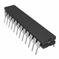
IC DAC 12BIT MULT LC2MOS 24-CDIP
Manufacturer
Analog Devices Inc
Datasheet
1.AD7845JNZ.pdf
(12 pages)
Specifications of AD7845SQ
Rohs Status
RoHS non-compliant
Settling Time
5µs
Number Of Bits
12
Data Interface
Parallel
Number Of Converters
1
Voltage Supply Source
Dual ±
Power Dissipation (max)
150mW
Operating Temperature
0°C ~ 70°C
Mounting Type
Through Hole
Package / Case
24-CDIP (0.300", 7.62mm)
Available stocks
Company
Part Number
Manufacturer
Quantity
Price


REV. B
UNIPOLAR BINARY OPERATION
Figure 13 shows the AD7845 connected for unipolar binary
operation. When V
Binary Number In
DAC Register
MSB
1111
1000
0000
0000
OFFSET AND GAIN ADJUSTMENT FOR FIGURE 13
Zero Offset Adjustment
1. Load DAC with all 0s.
2. Trim R3 until V
Gain Adjustment
1. Load DAC with all 1s.
2. Trim R1 so that V
In fixed reference applications, full scale can also be adjusted by
omitting R1 and R2 and trimming the reference voltage magni-
tude. For high temperature applications, resistors and potenti-
ometers should have a low temperature coefficient.
2-quadrant multiplication. The code table for Figure 13 is given
in Table I.
Table I. Unipolar Binary Code Table for AD7845
Figure 13. Unipolar Binary Operation
1111
0000
0000
0000
IN
OUT
OUT
is an ac signal, the circuit performs
= 0 V.
LSB
1111
0000
0001
0000
= –V
IN
4096
4095
Analog Output, V
–V
–V
–V
0 V
IN
IN
IN
.
4096
2048
4096
4096
4095
1
= –1/2 V
OUT
IN
–7–
BIPOLAR OPERATION
(4-QUADRANT MULTIPLICATION)
The recommended circuit for bipolar operation is shown in
Figure 14. Offset binary coding is used.
The offset specification of this circuit is determined by the
matching of internal resistors R
offset error of the device. Gain error may be adjusted by varying
the ratio of R1 and R2.
To use this circuit without trimming and keep within the gain
error specifications, resistors R1 and R2 should be ratio
matched to 0.01%.
The code table for Figure 14 is given in Table II.
Binary Number In
DAC Register
MSB
1111
1000
1000
0111
0000
Table II. Bipolar Code Table for Offset Binary Circuit of
Figure 14
Figure 14. Bipolar Offset Binary Operation
1111
0000
0000
1111
0000
LSB
1111
0001
0000
1111
0000
B
and R
C
Analog Output, V
+V
+V
0 V
–V
–V
and by the zero code
IN
IN
IN
IN
2048
2048
2048
2047
2048
2048
AD7845
1
1
= –V
OUT
IN
Related parts for AD7845SQ
Image
Part Number
Description
Manufacturer
Datasheet
Request
R

Part Number:
Description:
±1.7g Dual-Axis IMEMS Accelerometer Evaluation Board
Manufacturer:
Analog Devices Inc
Datasheet:

Part Number:
Description:
Inertial Sensor Evaluation System
Manufacturer:
Analog Devices Inc
Datasheet:
Part Number:
Description:
Manufacturer:
Analog Devices Inc
Datasheet:
Part Number:
Description:
Manufacturer:
Analog Devices Inc
Datasheet:
Part Number:
Description:
Manufacturer:
Analog Devices Inc
Datasheet:
Part Number:
Description:
Manufacturer:
Analog Devices Inc
Datasheet:
Part Number:
Description:
Manufacturer:
Analog Devices Inc
Datasheet:
Part Number:
Description:
Manufacturer:
Analog Devices Inc
Datasheet:
Part Number:
Description:
Manufacturer:
Analog Devices Inc
Datasheet:
Part Number:
Description:
Manufacturer:
Analog Devices Inc
Datasheet:
Part Number:
Description:
Manufacturer:
Analog Devices Inc
Datasheet:
Part Number:
Description:
Manufacturer:
Analog Devices Inc
Datasheet:
Part Number:
Description:
Manufacturer:
Analog Devices Inc
Datasheet: