PSK1212-9 POWER ONE, PSK1212-9 Datasheet - Page 17
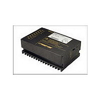
PSK1212-9
Manufacturer Part Number
PSK1212-9
Description
Manufacturer
POWER ONE
Type
Step Downr
Datasheet
1.PSK1212-9.pdf
(20 pages)
Specifications of PSK1212-9
Output Current
12A
Input Voltage
18 to 144V
Output Voltage
12V
Number Of Outputs
1
Output Power
144
Screening Level
Commercial
Operating Temperature Min Deg. C
-40C
Operating Temperature Max Deg. C
71C
Product Length (mm)
168.5mm
Product Depth (mm)
111mm
Product Height (mm)
80mm
Mounting Style
Screw
Pin Count
15
Lead Free Status / Rohs Status
Not Compliant


Description of Options
-9 Extended Temperature Range
This option defines an extended temperature range as
specified in table 10.
P Potentiometer to Adjust the Output
Option P excludes R function; the R-input (pin 16) should be
left open-circuit. The output voltage V
range 90 - 110% of V
However, the minimum differential voltage V
and output as specified in Electrical Input Data should be
maintained.
E Inrush Current Limitation
In regulators without option E, after application of the input
supply the inrush current is limited by parasitic components of
the voltage source and the regulator input only. The regulator
input exhibits a very low impedance, and when driven from a
low impedance source, for example a battery, the inrush
current can peak at several orders of magnitude above the
continuous input current.
Option E dramatically reduces this peak current and is
recommended for any application to protect series elements
such as fuses, switches, or circuit brakers. The startup circuit is
bypassed during normal operation.
C Thyristor Crowbar
Option C protects the load against power supply malfunction. It
is not designed to sink external currents.
As a central overvoltage protection device, the crowbar is
usually connected to the external load via distributed
inductance of the lines. For this reason, the overvoltage at the
load can temporarily exceed the trigger voltage V
Table 13: Crowbar trigger levels
BCD20029-G Rev AA, 28-Apr-09
Characteristics
V
t
s
Note: Option P is not recommended, if several regulators are
operated in parallel connection.
Note: This option requires an increased minimum input voltage
V
Note: The crowbar can be reset by removal of the input voltage
only. The inhibit signal cannot deactivate the thyristor.
1
o c
i max
Models with option P
Trigger voltage T
Delay time
of up to 1 V, dependent upon input range.
o nom
Conditions
V
I
o
C min
i min
= 0 – I
®
.
– V
– T
o nom
i max
C max
min typ
o
PSS5A12
PSK5A16
PSK5A20
PSK5A25
can be adjusted in the
6.3
1.5
i max
max min
6.7
between input
PSS1212
PSK1212
PSK1216
PSK1220
PSS129
14.3
Page 17 of 20
17.8
typ
1.5
o c
.
1
15.2
max min
18.9
Fig. 13
Option E: Inrush current versus time. R
(R
with V
Depending
overvoltage protection elements may have to be used
additionally.
A fixed-value monitoring circuit checks the output voltage V
and when the trigger voltage V
crowbar triggers and disables the output.
An external connection C (crowbar trigger control) is provided.
When crowbar option is used with two or more power supplies
in parallel connection, all crowbar trigger terminals (C) should
be interconnected. This ensures all crowbar circuits triggering
simultaneously, in order to disable all outputs at once. The
crowbar trigger voltage is maintained between Vo+ and Go–.
To prevent false triggering, the user should ensure that V
(between Vo+ and Go–) deos not exceed V
G RoHS Compliance
Models with G are RoHS-compliant for all six substances.
1
Î [A]
s
0
= 1
Inrush limit
i max
(
PSS2412
PSK2412
PSK2416
PSK2420
PSS249
I
i
28.89 30.6
= ––––
for models with V
typ
1.5
V
R
80 V)
i
s
on
Positive Switching Regulators
40 (typical)
max
)
PSS, PSK Series Data Sheet
the
min
Soft start
application,
PSS3612
PSK3612
PSK3616
PSK3620
PSS369
i max
43
typ
1.5
47
1
45.5
o c
max
80 V, R
50
100 (typical)
is reached, the thyristor
1
Normal operation
(R
s
further
min typ max
s
is the startup resistor
s
bypassed)
PSK 4812
= 15
PSS 489
o c
www.power-one.com
.
1.5
63
11029a
decentralized
for models
67
ms
t
Unit
μs
V
o
o
,
Related parts for PSK1212-9
Image
Part Number
Description
Manufacturer
Datasheet
Request
R

Part Number:
Description:
SWITCHING POWER SUPPLIES, SINGLE OUTPUT, 80 WATTS
Manufacturer:
POWER ONE
Datasheet:
Part Number:
Description:
HAS SERIES - 30 WATT
Manufacturer:
POWER ONE
Datasheet:
Part Number:
Description:
SINGLE OUTPUT
Manufacturer:
POWER ONE
Datasheet:

Part Number:
Description:
BRS DC/DC converters(1.5 WATT)
Manufacturer:
Power-One
Datasheet:
Part Number:
Description:
3...15 Watt DC-DC Converter
Manufacturer:
Power-One
Datasheet:
Part Number:
Description:
HBS SERIES - 100 WATT
Manufacturer:
Power-One
Datasheet:
Part Number:
Description:
3...15 Watt DC-DC Converter
Manufacturer:
Power-One
Datasheet:
Part Number:
Description:
BUS DC/DC converters(3 WATT)
Manufacturer:
Power-One
Datasheet:
Part Number:
Description:
HES SERIES 150 WATT
Manufacturer:
Power-One
Datasheet:
Part Number:
Description:
1.25 WATT
Manufacturer:
Power-One
Datasheet: