E2EM-C30X1-M1GJ-1 0.3M Omron, E2EM-C30X1-M1GJ-1 0.3M Datasheet - Page 5
E2EM-C30X1-M1GJ-1 0.3M
Manufacturer Part Number
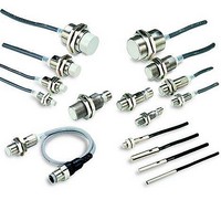
E2EM-C30X1-M1GJ-1 0.3M
Description
Proximity Sensors E2EM-C30X1 W/ M12 PI GTAIL CONN
Manufacturer
Omron
Datasheet
1.E2EM-C30X1-M1GJ-1_0.3M.pdf
(9 pages)
Specifications of E2EM-C30X1-M1GJ-1 0.3M
Lead Free Status / Rohs Status
Supplier Unconfirmed


I/O Circuit Diagrams
E2EM-X@X@ DC 2-Wire Models
E2EM-X@C@(-M1) DC 3-Wire Models
Connections for Sensor I/O Connectors
Operation
DC 2-wire
DC 3-wire
Operation mode
mode
Type
NO
NC
NO
NC
Output specifi-
Open-collector
Operation mode
cations
Proximity Sensor
output
NPN
E2EM-X4X1
E2EM-X8X1
E2EM-X15X1
E2EM-X16MX1
E2EM-X30MX1
E2EM-X4X2
E2EM-X8X2
E2EM-X15X2
E2EM-X16MX2
E2EM-X30MX2
NO
NO
NC
Model
Refer to the Sensor I/O Connector Group Catalog (Cat. No. X073) for details.
E2EM-X2C1(-M1)
E2EM-X4C@1-M1)
E2EM-X8C1(-M1)
E2EM-X15C1(-M1)
E2EM-X2C2
E2EM-X4C2
E2EM-X8C2
E2EM-X15C2
E2EM-X@X1-M1J
E2EM-X@C1-M1
E2EM-X@C2-M1
Model
Model
Sensing
object
Non-sensing
Sensing
object
(%)
(%)
Non-sensing area
area
Rated
sensing
distance
Rated
sensing
distance
Unstable
sensing
area
100
100
Sensing
object
Operation
indicator (yellow)
Control output
Sensing
object
Operation
indicator (yellow)
Control output
XS2F-D42@-@C0-A
XS2F-D42@-@80-A
Sensor I/O Connector
80
Sensing area
Timing chart
Set position
Stable sensing area
Not present
Not present
Timing chart
model
Present
Present
1: Straight
2: L-shape
1: Straight
2: L-shape
OFF
OFF
OFF
OFF
ON
ON
ON
ON
D: 2-m cable
G: 5-m cable
D: 2-m cable
G: 5-m cable
0
0
ON
OFF
ON
OFF
ON
OFF
ON
OFF
ON
OFF
Proximity Sensor
Proximity Sensor
Operation indicator
Setting indicator
(green)
Operation indicator
(red)
Control output
Control output
(red)
E2EM
E2EM
E2EM
E2EM
Note 1. The load can be connected to either the +V
Note 2. There is no polarity. Therefore, the brown
Note 3. Use pins 4 and 3 for NO.
Note: Use pin 4 for NO.
Use pin 2 for NC.
Proximity
Sensor
Proximity
circuit
Sensor
main
circuit
1
2
3
4
main
1
2
3
4
1
2
3
4
1
2
3
4
or 0 V side.
and blue lines have no polarity.
Use pins 1 and 2 for NC.
XS2F
XS2F
XS2F
XS2F
1
2
3
4
1
2
3
4
1
2
3
4
1
2
3
4
Connections
Output circuit
Output circuit
100 Ω
1
4
3
Brown
Black
or
Blue
4
3
2
Brown
or
or
Blue
1
2
Load
Load
Brown
(not connected)
Blue (+) (−)
Black (−) (+)
Brown (+V)
Blue (0 V)
Black (output)
Brown (+V)
White (not connected)
Blue (0 V)
Black (output)
Brown (+V)
White (output)
Blue (0 V)
Black
(not connected)
E2EM
(0 V)
(+V)
0 V
+V
0 V
+V
5
Related parts for E2EM-C30X1-M1GJ-1 0.3M
Image
Part Number
Description
Manufacturer
Datasheet
Request
R


Part Number:
Description:
G6S-2GLow Signal Relay
Manufacturer:
Omron Corporation
Datasheet:
Part Number:
Description:
Compact, Low-cost, SSR Switching 5 to 20 A
Manufacturer:
Omron Corporation
Datasheet:
Part Number:
Description:
Manufacturer:
Omron Corporation
Datasheet:
Part Number:
Description:
Manufacturer:
Omron Corporation
Datasheet:
Part Number:
Description:
Manufacturer:
Omron Corporation
Datasheet:
Part Number:
Description:
Manufacturer:
Omron Corporation
Datasheet:
Part Number:
Description:
Manufacturer:
Omron Corporation
Datasheet:
Part Number:
Description:
Manufacturer:
Omron Corporation
Datasheet: