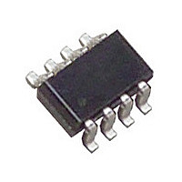
LT3092ITS8#PBF Linear Technology, LT3092ITS8#PBF Datasheet - Page 10

LT3092ITS8#PBF
Manufacturer Part Number
LT3092ITS8#PBF
Description
Manufacturer
Linear Technology
Datasheet
1.LT3092ITS8PBF.pdf
(22 pages)
Specifications of LT3092ITS8#PBF
Operating Temperature (max)
125C
Operating Temperature (min)
-40C
Pin Count
8
Mounting
Surface Mount
Package Type
TSOT-23
Case Length
2.9mm
Screening Level
Automotive
Lead Free Status / Rohs Status
Compliant
Available stocks
Company
Part Number
Manufacturer
Quantity
Price
LT3092
APPLICATIONS INFORMATION
Figure 3 depicts the simplest frequency compensation
network as a single capacitor connected across the two
terminals of the current source. In this case, either a
capacitor with a value less than 1000pF , or greater than
1μF (ESR < 0.5Ω), may stabilize the circuit. Some ap-
plications may use the small value capacitor to stand
off DC voltage, but allow the transfer of data down a
signal line.
For some applications, this capacitance range may be
unacceptable or present a design constraint. One circuit
example typifying this is an “intrinsically-safe” circuit in
which an overload or fault condition potentially allows
the capacitor’s stored energy to create a spark or arc.
For applications in which a single capacitor is unacceptable,
Figure 3 alternately shows a series RC network connected
across the two terminals of the current source. This network
has two benefi ts. First, it limits the potential discharge
current of the capacitor under a fault condition, preventing
sparks or arcs. Second, it bridges the gap between the
upper bound of 1000pF for small capacitors to the lower
bound of 1μF for large capacitors such that almost any
value capacitor can be used. This allows the user greater
fl exibility for frequency compensating the loop and fi ne
tuning the RC network for complex impedance networks.
In many instances, a series RC network is the best solution
for stabilizing the application circuit. Typical resistor values
will range from 100Ω to about 5k, especially for capacitor
10
Figure 3. Compensation From Input to
Output of Current Source Provides Stability
LT3092
SET
R
SET
10μA
+
–
IN
OUT
R
OUT
3092 F03
C
COMP
OR
R
COMP
C
COMP
values in between 1000pF and 1μF . Once again, Linear
Technology strongly recommends testing stability in situ
for any LT3092 application across all operating conditions,
especially ones that present complex impedance networks
at the input and output of the current source.
If an application refers the bottom of the LT3092 current
source to GND, it may be necessary to bypass the top
of the current source with a capacitor to GND. In some
cases, this capacitor may already exist and no additional
capacitance is required. For example, if the LT3092 was
used as a variable current source on the output of a power
supply, the output bypass capacitance would suffi ce to
provide LT3092 stability. Other applications may require
the addition of a bypass capacitor. Once again, the same
capacitor value requirements previously mentioned apply
in that an upper bound of 1000pF exists for small values
of capacitance, and a lower bound of 1μF (ESR < 0.5Ω)
exists for large value capacitors. A series RC network may
also be used as necessary, and depends on the application
requirements.
In some extreme cases, capacitors or series RC networks
may be required on both the LT3092’s input and output to
stabilize the circuit. Figure 4 depicts a general application
using input and output capacitor networks, rather than
an input-to-output capacitor. As the input of the current
source tends to be high impedance, placing a capacitor
on the input does not have the same effect as placing a
R
IN
C
IN
Figure 4. Input and/or Output Capacitors May
Be Used for Compensation
LT3092
3092 F04
SET
R
SET
10μA
+
–
V
IN
IN
OUT
R
I
OUT
OUT
C
OUT
OR
R
OUT
C
OUT
3092fb


