n
n
n
n
n
Typical applications
HVAC,security and industrial control, domestic appliances
04-2011, Rev. 0411
www.te.com
© 2011 Tyco Electronics Corporation,
a TE Connectivity Ltd. company
Approvals
VDE REG.-Nr 3919, UL E214024
Technical data of approved types on request
Contact Data
Contact arrangement
Rated voltage
Max. switching voltage
Rated current
Limiting making current, max 4s, df 10%
Breaking capacity max.
Contact material
Min. recommended contact load
Minimum switching voltage
Initial contact resistance
Frequency of operation, with/without load
Operate/release time max.
Bounce time max., form A/form B
Electrical endurance
Type
T75
T75
T75
T75
T75
Contact ratings
Type
T75
T75
T75
T75
T75
Mechanical endurance, DC coil
1 pole 8A, 1 form C (CO) or 1 form A (NO) contact
4kV/8mm coil-contact
Reinforced insulation (protection classII)
Ambient temperature up to 85°C at 8A
Plastic materials according to IEC60335-1 (domestic appliances)
Contact
A (NO)
B (NC)
Contact
A (NO)
C (CO)
C (CO)
C (CO)
C (CO)
Load
8Arms, 240VAC, resistive
14Arms, 120VAC, resistive
5Arms, 120VAC, resistive
7.2 FLA / 45 LRA, 120 VAC
5 FLA / 30 LRA, 240 VAC
Load
TV4, Tungsten, 120VAC, 40°C
10A, 240VAC, general purpose, 40°C
8A, 24VDC, general purpose, 40°C
1/3HP, 120VAC, 40°C
1/2HP, 240VAC, 40°C
1 form C (CO) or 1 form A (NO)
Datasheets and product specification
according to IEC 61810-1 and to be used
only together with the ‘Definitions’ section.
100mΩ at 100mA, 12VDC
10x10
100mA at 12VDC
6/1200min
250VAC
400VAC
2000VA
10/5ms
3/10ms
AgCdO
5VDC
6
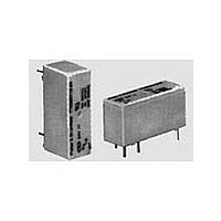
General Purpose Relays
PCB Relays
Low profile, PCB Relay T75 Series
15A
8A
operations
-1
100x10
100x10
50x10
50x10
30x10
10x10
25x10
30x10
30x10
Cycles
Cycles
6x10
3
3
3
3
3
3
3
3
3
3
Sensitive, Low Profile, Hi-Current
Relay Designed to Meet
International Standards
Features
• High sensitivity – nominal coil power requirement is as low as 212mW.
• Low profile, .591 in. (15mm) tall case uses only .465 in
• Power switching capability – contacts rated 10 amps in 1 Form A (SPST-NO) or 1
• Designed to meet UL, CSA, VDE, SEMKO and SEV requirements.
• Designed to meet VDE 8mm spacing, 4kV dielectric, coil to contacts.
• Designed to meet 3 mm creepage between contacts.
• Conforms to: VDE 0110 – Insulation Group C (250V)
• Wash tight (washable).
• Well suited for a broad range of applications e.g. HVAC, appliances,
Contact Ratings @ 25° C with relay properly vented.
Remove vent nib after soldering and cleaning.
Arrangements: 1 Form A (SPST-NO) and 1 Form C (SPDT).
Material: Silver-cadmium oxide.
Expected Mechanical Life: 10 million operations.
Expected Electrical Life:
Contact Ratings (See Figure 1):
VDE Contact Ratings: 8 amps, 250VAC.
UL Contact Ratings: 10 amps, 240VAC; 8 amps 24VDC;
Figure 1 - DC Switching Load Limit Curve
Datasheets and product data is subject to the
terms of the disclaimer and all chapters of
the ‘Definitions’ section, available at
http://relays.te.com/definitions
printed circuit board, permitting high density circuit design.
Form C (SPDT) arrangements.
security and industrial control.
Coil Data
Coil voltage range
Operative range, IEC 61810
Coil insulation system according UL
Coil versions, DC coil
1) Coil resistance ±15%
All figures are given for coil without pre-energization, at ambient temperature +23°C
Other coil voltages on request
Insulation Data
Initial dielectric strength
Clearance/creepage
Material group of insulation parts
Coil
code
03
05
06
09
12
24
48
60
300
200
100
50
40
30
20
100,000 operations at 8 amps, 240VAC.
50,000 operations at 14 amps NO / 5 amps NC, 120VAC Res.
30,000 operations at 7.2 FLA, 45 LRA, 120VAC.
10,000 operations at 5 FLA, 30 LRA, 240VAC.
30,000 operations at B300 pilot duty (360VA, 240VAC; 470VA, 120VAC).
Maximum Switched Voltage: 380VAC.
Maximum Switched Current: 14/5 (N.O./N.C.) amps, AC resistive;
Maximum Switched Power: 200W, DC; 2,000VA, AC.
between open contacts
between contact and coil
between contact and coil
Minimum Required Contact Load: 12V, 100mA.
voltage
Rated
VDC
12
24
48
60
VDE 435 Part 201 – High current applications
VDE 0804 – Telecommunications equipment
VDE 0631 – Temperature controllers and limiters
VDE 0700 – Household appliances
VDE 0805/5.90 – Office machines
3
5
6
9
1/3 HP, 120VAC; 1/2 HP, 240VAC.
Operate
voltage
16.3
32.6
40.8
VDC
2.1
3.4
4.1
6.1
8.2
8 amps DC (see Fig. 1)
Datasheets, product data, ‘Definitions’ sec-
tion, application notes and all specifications
are subject to change.
Release
voltage
VDC
Potter & Brumfield
0.3
0.5
0.6
0.9
1.2
2.4
4.8
6.0
V
3 to 60VDC
1000V
4000V
≥8/8mm
classA
resistance
Z
Ω±10%
15265
IIIa
2
2270
8790
118
165
364
652
Coil
40
2
rms
rms
(3cm
1)
1)
2
) of area on the
Rated coil
power
mW
225
212
218
223
221
254
262
236
Issued 3-03 (P
1
Catalo