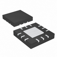
MAX5535ETC+ Maxim Integrated Products, MAX5535ETC+ Datasheet - Page 16

MAX5535ETC+
Manufacturer Part Number
MAX5535ETC+
Description
IC DAC 12BIT DUAL ULP 12-TQFN
Manufacturer
Maxim Integrated Products
Datasheet
1.MAX5532EUA.pdf
(24 pages)
Specifications of MAX5535ETC+
Settling Time
660µs
Number Of Bits
12
Data Interface
MICROWIRE™, QSPI™, Serial, SPI™
Number Of Converters
2
Voltage Supply Source
Single Supply
Power Dissipation (max)
1.35mW
Operating Temperature
-40°C ~ 85°C
Mounting Type
Surface Mount
Package / Case
12-TQFN Exposed Pad
Resolution
12 bit
Interface Type
Serial (3-Wire, SPI, QSPI, Microwire)
Supply Voltage (max)
5.5 V
Supply Voltage (min)
1.8 V
Maximum Operating Temperature
+ 85 C
Mounting Style
SMD/SMT
Minimum Operating Temperature
- 40 C
Lead Free Status / RoHS Status
Lead free / RoHS Compliant
Dual, Ultra-Low-Power,
12-Bit, Voltage-Output DACs
Table 2. Serial-Interface Programming Commands
X = Don’t care.
*Standby mode can be entered from normal operation only. It is not possible to enter standby mode from shutdown.
16
C3
0
0
0
0
0
0
0
0
1
1
1
1
1
1
1
1
______________________________________________________________________________________
CONTROL BITS
C2
0
0
0
0
1
1
1
1
0
0
0
0
1
1
1
1
C1
0
0
1
1
0
0
1
1
0
0
1
1
0
0
1
1
C0
0
1
0
1
0
1
0
1
0
1
0
1
0
1
0
1
XXXXXXXXXXXX
INPUT DATA
XXXXXXXXXX
XXXXXXXXXX
XXXXXXXXXX
12–bit data
12-bit data
12-bit data
12-bit data
12-bit data
12-bit data
D11, D10,
D11, D10,
D11, D10,
D11–D0
—
—
—
—
—
—
No operation; command is ignored.
Load input register A from shift register; DAC registers unchanged; DAC
outputs unchanged.
Load input register B from shift register; DAC registers unchanged; DAC
outputs unchanged.
Command reserved. Do not use.
Command reserved. Do not use.
Command reserved. Do not use.
Command reserved. Do not use.
Command reserved. Do not use.
Load DAC registers A and B from respective input registers; DAC outputs A
and B updated; MAX5533/MAX5535 enter normal operation if in standby or
shutdown; MAX5532/MAX5534 enter normal operation if in shutdown.
Load input register A and DAC register A from shift register; DAC output A
updated; Load DAC register B from input register B; DAC output B updated;
MAX5533/MAX5535 enter normal operation if in standby or shutdown;
MAX5532/MAX5534 enter normal operation if in shutdown.
Load input register B and DAC register B from shift register; DAC output B
updated; Load DAC register A from input register A; DAC output A updated;
MAX5533/MAX5535 enter normal operation if in standby or shutdown;
MAX5532/MAX5534 enter normal operation if in shutdown.
Command reserved. Do not use.
MAX5533/MAX5535 enter standby*, MAX5532/MAX5534 enter shutdown. For
the MAX5533/MAX5535, D11 and D10 configure the internal reference voltage
(Table 3).
MAX5532–MAX5535 enter normal operation; DAC outputs reflect existing
contents of DAC registers. For the MAX5533/MAX5535, D11 and D10
configure the internal reference voltage (Table 3).
MAX5532–MAX5535 enter shutdown; DAC outputs set to high impedance. For
the MAX5533/MAX5535, D11 and D10 configure the internal reference voltage
(Table 3).
Load input registers A and B and DAC registers A and B from shift register;
DAC outputs A and B updated; MAX5533/MAX5535 enter normal operation if
in standby or shutdown; MAX5532/MAX5534 enter normal operation if in
shutdown.
FUNCTION


