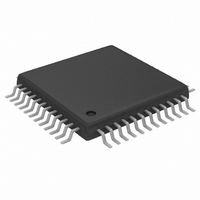
MAX5858ECM+TD Maxim Integrated Products, MAX5858ECM+TD Datasheet - Page 14

MAX5858ECM+TD
Manufacturer Part Number
MAX5858ECM+TD
Description
IC DAC 10BIT DUAL 300MSPS 48TQFP
Manufacturer
Maxim Integrated Products
Datasheet
1.MAX5858ECMD.pdf
(23 pages)
Specifications of MAX5858ECM+TD
Settling Time
11ns
Number Of Bits
10
Data Interface
Parallel
Number Of Converters
2
Voltage Supply Source
Single Supply
Power Dissipation (max)
816mW
Operating Temperature
-40°C ~ 85°C
Mounting Type
Surface Mount
Package / Case
48-TQFP Exposed Pad, 48-eTQFP, 48-HTQFP, 48-VQFP
Lead Free Status / RoHS Status
Lead free / RoHS Compliant
At power-up, the MAX5858’s default configuration is
no-interpolation mode with a gain of 0dB and a fully
operational converter. In shutdown, the MAX5858 con-
sumes only 1µA of supply current, and in standby the
current consumption is 4.4mA. Wake-up time from
standby mode to normal operation is 0.7µs.
The MAX5858 features a two stage, 2x digital interpo-
lating filter based on 43-tap and 23-tap FIR topology.
F1EN and F2EN enable the interpolation filters. F1EN
high enables the first filter for 2x interpolation and F2EN
high enables the second filter for combined 4x interpo-
lation. To bypass and disable both interpolation filters
(no-interpolation mode or 1x mode) set F1EN = F2EN =
0. When set for 1x mode the filters are powered down
and consume virtually no current. An illegal condition is
defined by: F1EN = 0, F2EN = 1 (see Table 2 for con-
figuration modes).
Dual, 10-Bit, 300Msps, Current-Output DAC with
4x/2x/1x Interpolation Filters
Table 1. Control Word Format and Function
Table 2. Configuration Modes
X = Don’t care.
F1EN = 0, F2EN = 1 illegal.
14
CONTROL WORD
No interpolation
2x interpolation
4x interpolation
Power-down
MSB
PD
Power-up
______________________________________________________________________________________
Standby
MODE
DACEN
F2EN
F1EN
PD
G3
G2
G1
G0
DACEN
Power-Down. The part enters power-down mode if PD = 1.
DAC Enable. When DACEN = 0 and PD = 0, the part enters standby mode.
Filter Enable. When F2EN = 1 and F1EN = 1, 4x interpolation is enabled. When F2EN = 0, the interpolation
mode is determined by F1EN.
Filter Enable. When F1EN = 1 and F2EN = 0, 2x interpolation is active. With F1EN = 0 and F2EN = 0, the
interpolation is disabled.
Bit 3 (MSB) of Gain Adjust Word.
Bit 2 of Gain Adjust Word.
Bit 1 of Gain Adjust Word.
Bit 0 (LSB) of Gain Adjust Word.
PD
0
0
0
0
1
0
F2EN
Device Power-Up and
DACEN
Interpolation Filters
States of Operation
1
1
1
0
X
1
F1EN
F2EN
0
0
1
X
X
X
F1EN
0
1
1
X
X
X
G3
The programmable interpolation filters multiply the
MAX5858 input data rate by a factor of 2x or 4x to sep-
arate the reconstructed waveform spectrum and the
first image. The original spectral images, appearing
around multiples of the DAC input data rate, are attenu-
ated at least 60dB by the internal digital filters. This fea-
ture provides three benefits:
1)
2)
3)
Figure 2 shows an application circuit and Figure 3 illus-
trates a practical example of the benefits when using
the MAX5858 in 4x-interpolation mode. The example
illustrates signal synthesis of a 20MHz IF with a
±10MHz bandwidth. The designer can consider three
options to address the design challenge. The tradeoffs
for each solution are depicted in Table 4.
Table 3. Gain Difference Setting
G2
FUNCTION
GAIN ADJUSTMENT ON
Image separation reduces complexity of analog
reconstruction filters.
Lower input data rates eliminate board level high-
speed data transmission.
Sin(x)/x roll-off is reduced over the effective band-
width.
CHANNEL A (dB)
-0.35
+0.4
G1
0
G0
G3
0
1
1
X
G2
0
0
1
G1
0
0
1
LSB
X
G0
0
0
1


