262-75 Xicon, 262-75 Datasheet - Page 2
262-75
Manufacturer Part Number
262-75
Description
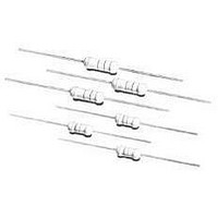
Metal Oxide Resistors 75ohms 5% Tol
Manufacturer
Xicon
Datasheet
1.281-470.pdf
(3 pages)
Specifications of 262-75
Resistance
75 Ohms
Tolerance
5 %
Power Rating
2 Watts
Temperature Coefficient
+/- 350 PPM / C
Termination Style
Axial
Operating Temperature Range
- 55 C to + 235 C
Dimensions
5.5 mm Dia. x 16 mm L
Product
Power Resistors Metal Oxide
Lead Free Status / Rohs Status
Lead free / RoHS Compliant
Available stocks
Company
Part Number
Manufacturer
Quantity
Price

Company:
Part Number:
262-75ABE-05
Manufacturer:
WAK
Quantity:
5 000
Company:
Part Number:
262-75ABE01
Manufacturer:
WAK
Quantity:
9 600
Company:
Part Number:
262-75ABE375
Manufacturer:
WAK
Quantity:
10 000


XC-600043
Metal Oxide Power Resistors
No.
Characteristics
DC. Resistance
Temperature
coefficient
Short time
overload
Dielectric
withstanding
voltage
Pulse overload
Terminal
strength
Resistance to
soldering heat
Solderability
1
2
3
4
5
6
7
CONSTRUCTION
CHARACTERISTICS
Specifications are subject to change without notice. No liability or warranty implied by this information. Environmental compliance based on producer documentation.
Basic
Resistance Film
End Cap
Lead Wire
Joint
Coating
Color Code
Name
BodyRod Type Ceramics
Metal Oxide Film
Steel (Tin plated iron surface)
Annealed copper wire
(Electrosolder plated surface) Pb Free
By welding
Insulated & Non-Flame Paint (Color : Sea-Blue )
Non-Flame epoxy resin
Must be within the specified
tolerance.
Within the temperature
coefficient specified below
±350 PPM / °C
Resistance change rate is
± (2 % + 0.05Ω) Max. with no
evidence of mechanical damage
No evidence of flashover
mechanical damage,arcing or
insulation break down.
Resistance change rate is
±(5% +0.05Ω) Max. with no
evidence of mechanical damage
With no evidence of mechanical
damage.
Resistance change rate is
± (1% + 0.05Ω) Max. with no
evidence of mechanical damage.
95 % coverage Min.
XICON PASSIVE COMPONENTS • (800) 628-0544
Material
Limits
Test Methods ( JIS C 5201-1 )
5.1 The limit of error of measuring apparatus
shall not exceed allowable range or 5% of
resistance tolerance
5.2 Natural resistance change per temp.
degree centigrade.
R
R
R
R
5.5 Permanent resistance change after the
application of a potential of 2.5 times RCWV
or the max overload voltage respectively specified
in the above list, whichever less for 5 seconds.
5.7 Resistors shall be clamped in the trough
of a 90° metallic V-block and shall be tested
at AC potential respectively specified in the
table 1 for 60 + 10/-0 seconds.
5.8 Resistance change afther 10,000 cycles
(1 second “on”, 25 seconds “off”) at 4 times
RCWV or the max. pulse overload voltage
6.1 Direct load
Resistance to a 2.5 kgs direct load for 10 secs.
in the direction of the longitudinal axis of the terminal leads.
Twist test :
Terminal leads shall be bent through 90° at a point of about
6mm from the body of the resistor and shall be rotated through 360°
about the original axis of the bent terminal in alternating direction
for a total of 3 rotations.
6.4 Permanent resistance change when leads
immersed to 3.2 to 4.8 mm from the body in
350 °C ± 10°C solder for 3 ± 0.5 seconds
6.5 The area covered with a new , smooth
clean , shiny and continuous surface free
from concentrated pinholes.
Test temp. of solder : 245°C ± 3°C
Dwell time in solder : 2 ~ 3 seconds
2
1
1
2
-R
(t
: Resistance value at room temperature (t
: Resistance value at room temp.plus 100°C (t
2
1
-t
1
)
4
x10
6
(PPM/°C)
6
1
2
3
MO Series
1
)
5
Date Revised: 9/28/05
2
)
Related parts for 262-75
Image
Part Number
Description
Manufacturer
Datasheet
Request
R

Part Number:
Description:
Metal Oxide Resistors USE 262-150K/REEL-RC 5% Tol
Manufacturer:
Xicon
Datasheet:
Part Number:
Description:
Metal Oxide Resistors USE 262-39K/REEL-RC
Manufacturer:
Xicon
Datasheet:
Part Number:
Description:
Metal Oxide Resistors USE 262-22K/REEL-RC 5% Tol
Manufacturer:
Xicon
Datasheet:
Part Number:
Description:
Metal Oxide Resistors USE 262-820/REEL-RC
Manufacturer:
Xicon
Datasheet:
Part Number:
Description:
Metal Oxide Resistors USE 262-33/REEL-RC
Manufacturer:
Xicon
Datasheet:
Part Number:
Description:
Metal Oxide Resistors USE 262-270/REEL-RC 5% Tol
Manufacturer:
Xicon
Datasheet:
Part Number:
Description:
Metal Oxide Resistors USE 262-680K/REEL-RC
Manufacturer:
Xicon
Datasheet:
Part Number:
Description:
Metal Oxide Resistors USE 262-20-RC 5% Tol
Manufacturer:
Xicon
Datasheet:
Part Number:
Description:
Metal Oxide Resistors USE 262-910/REEL-RC
Manufacturer:
Xicon
Datasheet:
Part Number:
Description:
Metal Oxide Resistors USE 262-2.0/REEL-RC
Manufacturer:
Xicon
Datasheet:


Part Number:
Description:
Standard LED - Through Hole Red Water Clear
Manufacturer:
Xicon
Datasheet:

Part Number:
Description:
Standard LED - Through Hole Yellow Water Clear
Manufacturer:
Xicon
Datasheet:

Part Number:
Description:
Standard LED - Through Hole Blink Red Diffused
Manufacturer:
Xicon
Datasheet:

Part Number:
Description:
Standard LED - Through Hole Green Diffused
Manufacturer:
Xicon
Datasheet: