75-068014-06S Amphenol, 75-068014-06S Datasheet - Page 161
75-068014-06S
Manufacturer Part Number
75-068014-06S
Description
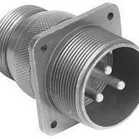
Circular MIL / Spec Connectors 6P 97 Series MIL-DTL-5015
Manufacturer
Amphenol
Series
97 Seriesr
Datasheet
1.M3902932-260.pdf
(436 pages)
Specifications of 75-068014-06S
Mil Type
MIL-DTL-5015
Product Type
Connectors
Contact Style
Socket (Female)
Shell Style
Receptacle
Shell Size
14S
Number Of Contacts
6
Insert Arrangement
14S-6
Mounting Style
Panel
Termination Style
Crimp
Contact Type
Socket
Shell Plating
Chromate over Cadmium, Olive Drab
Contact Plating
Silver
Voltage Rating
250 V
Body Material
Aluminum
Mounting Angle
Straight
Lead Free Status / Rohs Status
Lead free / RoHS Compliant


160
Contact Amphenol Aerospace for more information at 800-678-0141 • www.amphenol-aerospace.com
† When fully mated with plug this band will be covered.
Bayonet coupling connectors are offered in Military 83723 and Commercial equivalent
designations. They are not included in Boeing, GE, ASD and other European specified
connectors.
Shell size 28 is not available in Bayonet coupling connectors.
All dimensions for reference only.
A
Amphenol
(Band is red on military types; can be red or blue on
commercial types).
Shell
Shell
Size
Size
B
10
12
14
16
18
20
22
24
10
12
14
16
18
20
22
24
8
8
4 Mounting Holes
Shell Sizes 8 to 22 –
Shell Sizes 24 & 28 –
.125/.116
.154/.145
±.005
1.031
1.125
1.250
1.343
1.437
1.562
1.703
±.005
20.62
23.80
26.19
28.58
31.75
34.11
36.50
39.67
43.26
.812
.937
Aerospace
A
B
A
A
3.17/2.94
3.91/3.68
±.005
1.062
1.156
1.250
1.375
±.005
15.04
18.26
20.62
23.01
24.61
26.97
29.36
31.75
34.93
.594
.719
.812
.906
.969
B
B
X Dia.
Panel
Fully Mated
Band†
Min.
P Dia.
Front
Max.
D Dia.
Panel
D Dia.
1.010
1.072
1.192
1.322
1.447
Panel
12.95
16.13
19.30
22.48
25.65
27.23
30.28
33.58
36.75
Min.
Min.
.510
.635
.760
.885
MIL-DTL-83723, Series III, Pyle
Square Flange Receptacle, Bayonet Coupling
.250 Max.
6.35 Max.
1.375 Max.
34.92 Max.
F Dia.
1.000
1.062
1.187
1.312
1.437
F Dia.
12.70
15.88
19.05
22.23
25.40
26.97
30.15
33.32
36.50
Rear
Max.
Rear
Max.
.500
.625
.750
.875
.125 Max.
3.17 Max.
H Accessory Thread
Accessory Thread
1.0000-20 UNEF
1.0625-18 UNEF
1.1875-18 UNEF
1.3125-18 UNEF
1.4375-18 UNEF
P Dia.
Front
14.27
17.68
22.23
23.77
26.97
30.15
33.32
36.50
39.67
.5000-20 UNF
.6250-24 UNEF
.7500-20 UNEF
.8750-20 UNEF
Max.
Class 2A
F Dia.
Rear
Max.
H
3 Teeth
Equally Spaced 120° Apart
Blue Band Indicates
Rear Release Contact System
D Dia.
Millimeters
Panel
Min.
X Dia.
Panel
15.75
18.99
23.19
24.89
28.12
30.71
33.96
36.88
40.06
Min.
Optional 360°
Accessory Teeth
1.062
1.187
1.312
1.437
1.562
P Dia.
Front
.562
.696
.875
.936
Max.
See Quick Reference page 143 for the variety of
ordering options for square flange receptacles with
bayonet coupling.
The How to Order page 149 gives complete part
number breakdowns.
1.107
1.209
1.337
1.452
1.577
X Dia.
Panel
.620
.748
.913
.980
Min.
Inches
PART #
®
PART #
M83723/71 / M83723/72
BY( )-17
Related parts for 75-068014-06S
Image
Part Number
Description
Manufacturer
Datasheet
Request
R

Part Number:
Description:
CBL BNC ST PLUG-PLG BEL 8218 36"
Manufacturer:
Amphenol Connex
Datasheet:
Part Number:
Description:
CBL BNC ST PLUG-PLG BEL 8218 24"
Manufacturer:
Amphenol Connex
Datasheet:
Part Number:
Description:
CBL BNC ST PLUG-PLG BEL 8218 12"
Manufacturer:
Amphenol Connex
Datasheet:
Part Number:
Description:
CBL BNC ST PLUG-PLUG BEL 8218 6"
Manufacturer:
Amphenol Connex
Datasheet:

Part Number:
Description:
CBL BNC ST PLUG-PLG BEL 8218 48"
Manufacturer:
Amphenol Connex
Datasheet:


Part Number:
Description:
Cable Specification: PU CABLE, UL20549 24AWG*8C+AD,OD= 6.0mm
Manufacturer:
Amphenol