91-569705-35P Amphenol, 91-569705-35P Datasheet - Page 35
91-569705-35P
Manufacturer Part Number
91-569705-35P
Description
Circular MIL / Spec Connectors 20P LJT Series MIL-DTL-38999 I
Manufacturer
Amphenol
Series
JT Seriesr
Datasheet
1.91-569762-35G.pdf
(53 pages)
Specifications of 91-569705-35P
Mil Type
MIL-DTL-38999 II
Product Type
Connectors
Contact Style
Pin (Male)
Shell Style
Receptacle
Shell Size
17
Number Of Contacts
55
Insert Arrangement
17-35
Mating Style
Bayonet
Mounting Style
PCB
Termination Style
Solder Pin
Shell Plating
Electroless Nickel
Mounting Angle
Straight
Lead Free Status / Rohs Status
Lead free / RoHS Compliant


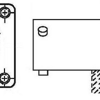
MIL-DTL-38999 Series I Type Connectors
with PCB contacts
LJT07R jam nut receptacle
HOW TO ORDER
• Order by applicable 88/91 part number in table below.
• Add insert arrangement to end of number. Refer to insert availability chart on page 4 and
• Z dimension is determined by contact type in the insert arrangement.
• Most common options are shown; other options are available.
All dimensions for reference only.
Shell
Size
11
13
15
17
19
21
23
25
88 prefix designates olive drab cadmium plated connector shell.
91 prefix designates electroless nickel plated connector shell.
pin-out illustrations on pages 4-24. Last letter of part number designates rotation; P for
pins in normal position, S for sockets in normal position. See page 25 for alternate rota-
tion letter to use.
Example part number: 88-569721-35P designates shell size 9 with a 9-35 insert and pin
contacts in normal position.
9
88/91-569721-XXX
Part Number
722-XXX
723-XXX
724-XXX
725-XXX
726-XXX
727-XXX
728-XXX
729-XXX
+.000
–.010
1.084
1.208
1.333
1.459
1.580
1.709
T
.669
.769
.955
C
H
S
A*
1.199
1.386
1.511
1.636
1.761
1.949
2.073
2.199
2.323
Max.
C
H Hex
+.017
–.016
1.000
1.188
1.312
1.438
1.562
1.688
1.812
2.000
.875
Max.
.625
.625
.625
.625
.625
.656
.750
.750
.750
L
+.001
–.005
1.100
1.207
1.332
1.457
1.582
.572
.700
.850
.975
A*
N
N
±.016
1.062
1.250
1.375
1.500
1.625
1.812
1.938
2.062
2.188
31
S
+.010
–.000
1.007
1.134
1.259
1.384
1.507
1.634
1.759
.697
.822
T*
.915 .005
RR
THREAD
1.0625-18 UNEF
1.1875-18 UNEF
1.3125-18 UNEF
1.4375-18 UNEF
.4375-28 UNEF
.5625-24 UNEF
.6875-24 UNEF
.8125-20 UNEF
.9375-20 UNEF
V Thread
Class 2A
(Plated)
★
*
.059 dia. min. 3 lockwire holes.
Formed lockwire hole design (6 holes) is optional.
“D” shaped mounting hole dimensions
.062 MIN.
.125 MAX PANEL THICKNESS
1.0000-20 UNEF .229 – .175 .243 – .182
1.1250-18 UNEF .229 – .175 .243 – .182
1.2500-18 UNEF .229 – .175 .243 – .182
1.3750-18 UNEF .207 – .158 .221 – .165
1.5000-18 UNEF .207 – .158 .221 – .165
1.6250-18 UNEF .207 – .158 .221 – .165
1.7500-18 UNS
.6875-24 UNEF .229 – .175 .243 – .182
.8125-20 UNEF .229 – .175 .243 – .182
RR Thread
Class 2A
.328 MAX.
(Plated)
V THREAD
.062
FOR SIZE 16 CONTACT
.019 .001 DIA.
FOR SIZE 20 & 22D
CONTACTS
Z
PCB TAIL STICKOUT
.001 DIA.
.207 – .158 .221 – .165
Contacts
16 & 20
Size
Z
Contacts
Size 22D
Related parts for 91-569705-35P
Image
Part Number
Description
Manufacturer
Datasheet
Request
R


Part Number:
Description:
Cable Specification: PU CABLE, UL20549 24AWG*8C+AD,OD= 6.0mm
Manufacturer:
Amphenol