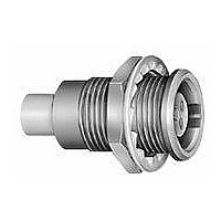
EGN.2F.319.XLM LEMO, EGN.2F.319.XLM Datasheet - Page 8

EGN.2F.319.XLM
Manufacturer Part Number
EGN.2F.319.XLM
Description
Circular Push Pull Connectors 19P RECEPT FEMALE CRIMP CONTACTS
Manufacturer
LEMO
Series
F Seriesr
Datasheet
1.FGN.0F.304.XLC.pdf
(48 pages)
Specifications of EGN.2F.319.XLM
Product Type
Connectors
Contact Style
Socket (Female)
Shell Style
Receptacle
Number Of Contacts
19
Lead Free Status / Rohs Status
Lead free / RoHS Compliant
Selection of contact types
Crimp contacts
The crimp contacts are designed to be crimped with the
standard four indent method according to MIL-C-22520F,
class 1, type 1.
A detailed range of conductor dimensions that can be
crimped into our contacts is given on the table at right. See
also the section on tooling (pages 30 to 33).
Print contacts
Print contacts are available in straight or elbow versions
for certain connector types. Connection is possible by sol-
dering on flexible or rigid printed circuit boards.
Straight print contacts are gold-plated which guarantees
optimum soldering, even after longterm storage.
Fibre Optic contacts
The new miniature F7 fibre optic contact is available for use
with single-mode or multi-mode fibres of the following
sizes; 9/125, 50/125 and 62.5/125 microns.
Contacts are designed with the IEC standard 1.25 mm dia-
meter ceramic ferrules. After mounting on the cable, the
6
Fig. 1
Fig. 2
straight
1
2
3
4
5
ø A
®
Female contact
body with holder
ferrule with holder
spring
crimp ferrule
alignment tube
with support
ø A
ø A
ø A
ø A
®
L
ø C
4
ø A
1
3
ø C
ø C
ø C
ø C
2
L
ø C
5
Contacts are provided in two forms: with a standard crimp
barrel for large conductors (see fig. 1), or with a reduced
crimp barrel for smaller conductors (see fig. 2).
Note: Fr = mean contact retention force in the insulator (according to IEC
60512-8 test 15a).
Note:
designs is larger than the solder cup diameter. Make sure that the maxi-
mum conductor diameter is smaller than ø C.
Print elbow contacts include a tinned copper wire crimped
into a contact.
L dimensions and C ø are detailed in the section on model
description (elbow: L = 2 mm).
contact is very easily installed in the connector insulator,
the particular shape of the contact body retains it in the
insulator. The alignment tube can be easily removed in
order to clean the fibre end face.
(mm) (mm) per fig.
(mm) (mm) per fig.
elbow
ø A
ø A
0.5
0.7
0.9
1.3
0.7
0.9
1.3
Contact
Contact
1)
0.42
0.80
1.10
1.40
0.45
0.80
0.45
1.10
ø C
ø C
for a given AWG, the diameter of some stranded conductor
Form
Form
2
1
1
1
1
2
2
2
2
ø A
3
AWG stranded
AWG stranded
min.
min.
32
26
24
20
32
26
32
24
1
Conductor stranded
Conductor stranded
max.
max.
28
22
20
18
28
22
28
20
4
1)
1)
1)
0.035
0.140
0.250
0.500
0.035
0.140
0.035
0.250
Section (mm
Section (mm
min.
min.
L
1
2
3
4
ø C
Male contact
body with holder
ferrule with holder
spring
crimp ferrule
max.
max.
0.09
0.34
0.50
1.00
0.09
0.34
0.09
0.50
2
2
)
)
www.lemo.com
(N)
(N)
12
22
30
40
22
30
40
F
F
r
r


