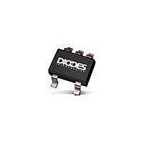
AP131-30WL-7 Diodes Inc, AP131-30WL-7 Datasheet - Page 4

AP131-30WL-7
Manufacturer Part Number
AP131-30WL-7
Description
Low Dropout (LDO) Regulators LDO CMOS 300MA 0.5V VOUT+0.5V-7.0V 3.0V
Manufacturer
Diodes Inc
Datasheet
1.AP131-20WL-7.pdf
(7 pages)
Specifications of AP131-30WL-7
Number Of Outputs
1
Polarity
Positive
Input Voltage Max
5.5 V
Output Voltage
3 V
Output Type
Fixed
Dropout Voltage (max)
0.5 V at 300 mA
Output Current
300 mA
Line Regulation
0.3 % / V
Load Regulation
35 mV
Voltage Regulation Accuracy
2 %
Maximum Power Dissipation
0.25 W
Maximum Operating Temperature
+ 85 C
Mounting Style
SMD/SMT
Package / Case
SOT-25
Minimum Operating Temperature
- 40 C
Lead Free Status / Rohs Status
Lead free / RoHS Compliant
Available stocks
Company
Part Number
Manufacturer
Quantity
Price
Company:
Part Number:
AP131-30WL-7
Manufacturer:
DIODES
Quantity:
30 000
Part Number:
AP131-30WL-7
Manufacturer:
DIODES/美台
Quantity:
20 000
Company:
Part Number:
AP131-30WL-7-F
Manufacturer:
DIODES
Quantity:
30 000
Part Number:
AP131-30WL-7-F
Manufacturer:
DIODES/美台
Quantity:
20 000
Electrical Characteristics
T
Notes:
AP131 Rev. 7
A
= 25ºC, C
Symbol
ΔV
V
ΔV
PSRR
T
ΔV
V
V
I
I
ENOFF
DELAY
LIMIT
θ
θ
DROP
short
I
ENON
I
I
SB
EN
LOAD
Q
JA
JC
LINE
3. Dropout voltage is defined as the input to output differential voltage. Dropout is measured at constant junction temperature by using pulsed ON
OUT
4. Current limit is measured at constant junction temperature by using pulsed testing with a low ON time.
5. Regulation is measured at constant junction temperature by using pulsed testing with a low ON time.
6. Guaranteed by design.
7. Test conditions for SOT25: Device mounted on FR-4 substrate PC board, 2oz copper, with minimum recommended pad layout.
time, and the criterion is V
IN
= 1µF, C
Dropout Voltage (Note 3)
Current Limit (Note 4)
Short Circuit Current
Line Regulation
Load Regulation (Note 5)
Output Voltage Accuracy
Output Voltage Temperature
Coefficient (Note 6)
Ripple Rejection
Standby Current
Quiescent Current
Enable Pin Current
Enable Pin Voltage
Enable Delay Time
Thermal Resistance
Junction-to-Ambient
Thermal Resistance
Junction-to-Case
OUT
Parameter
= 10µF, unless otherwise specified.
OUT
inside target value ±2%. This test is skipped at the condition of V
300mA LOW DROPOUT LINEAR REGULATOR WITH
www.diodes.com
I
V
V
I
to 5.5V
I
I
F = 100Hz,
C
I
I
I
Output ON
Output OFF
C
I
SOT25 (Note 7)
SOT25 (Note 7)
L
OUT
L
L
L
L
L
OUT
4 of 7
IN
OUT
IN
BP
= 300mA
= 1~300mA, V
= 1mA, V
= 100mA
= 0mA, V
= 0mA, V
= 5V, V
= 1μF, C
=1mA, V
= 0.1μF, C
= 30mA
< 1.05V
Conditions
OUT
IN
IN
IN
O
IN
= 5V
= 5V, EN = 0V
= 5V, EN = 5V
= 10uF,
= 0V
=( V
OUT
IN
= 5V
= 1μF,
OUT
+1V )
IN
<3V.
Min
350
1.5
-2
0
-
-
-
-
-
-
-
-
-
-
Typ.
400
450
150
163
0.1
30
50
60
50
53
8
-
-
-
-
-
FEBRUARY 2009
©
SHUTDOWN
Diodes Incorporated
AP131
< 0.1
Max
500
300
150
100
0.3
0.8
V
35
+2
5
-
-
-
IN
PPM/
O
O
Unit
%/V
mV
mA
mA
mV
C/W
C/W
dB
μA
μA
μA
μS
ºC
%
V
V


