142-4308-406 Emerson Network Power, 142-4308-406 Datasheet - Page 220
142-4308-406
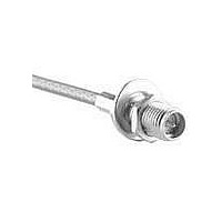
Manufacturer Part Number
142-4308-406
Description
RF Connectors BLHD JCK 142/400 Ni
Manufacturer
Emerson Network Power
Datasheet
1.133-3711-801.pdf
(294 pages)
Specifications of 142-4308-406
Product
Connector
Rf Series
SMA
Gender
Receptacle
Polarity
Reverse
Contact Plating
Gold
Shell Plating
Nickel
Impedance
50 Ohms
Termination Style
Crimp
Cable Type
RG 316/U, 188, 161, 174
Connector Type
Jack Crimp
Lead Free Status / Rohs Status
Lead free / RoHS Compliant


220
Assembly Instructions
INCHES (MILLIMETERS) • CUSTOMER DRAWINGS AVAILABLE ON REQUEST
SMK Solder Type Straight Plugs for Semi-Rigid Cable
Connectivity Solutions
BEAD ASSEMBLY TOOL
.000 - .005 RECESSION
BEAD TO BODY
BEAD
Tel: 800-247-8256
PLUNGER
•
Fax: 507-833-6287
Contact Soldering Tool
4.
Semi-Rigid Cable Vise
1.
2.
3.
5.
6.
Body Soldering Tool
Cable Clamp Insert
Bead Assy. Tool
•
Identify connector parts (5 piece parts) and tools (5 tools.)
Strip cable jacket and dielectric to dimension shown.
Place center contact onto center conductor. Slide contact
soldering tool onto contact. Clamp the cable contact
and tool into cable soldering vise and solder contact to
center conductor. High temperature solder, such as
95/5 Sn/Ag is recommended so that contact solder joint
remains stable during body soldering operation. Solder
paste is recommended for the contact solder joint
to minimize excess solder. The assembled contact
dimension should be as shown.
Remove excess solder from contact with a sharp blade
and clean contact. Check for presence of excess
solder by sliding body soldering tool over the contact.
Remove soldering tool.
Place connector nut and body on cable. Place connector
body soldering tool over contact and thread the
coupling nut and connector body firmly to the tool. Place
cable subassembly into cable soldering vise. Clamp
cable and soldering tool securely to insure the cable
dielectric expansion will not disturb the cable in the vise
during soldering. Place hot soldering iron on the
connector body sleeve and apply solder from the
opposite side. A low temp solder, such as 60/40 Sn/Pb
is recommended for the body solder joint. Allow the
soldered joint to cool and remove from fixture. Check
contact location to the body. The best electrical results
are achieved when the contact location is within a tol-
erance of .060 +/- .001.
Place bead onto neck portion of the tool. Thread Bead
Assembly tool firmly into the coupling nut. Push the tool’s
plunger between your thumb and fingers to assemble
the bead. Check bead location. Assemble seal ring onto
body.
www.EmersonNetworkPower.com/connectivity
Vise Stop
TOOL
145-0693-001/002 145-0694-001/002
(for .086 Semi-Rigid)
140-0000-962
140-0000-968
140-0000-957
140-0000-960
140-0000-958
140-0000-964
(for .141 Semi-Rigid)
140-0000-962
140-0000-968
140-0000-957
140-0000-961
140-0000-959
140-0000-965
Related parts for 142-4308-406
Image
Part Number
Description
Manufacturer
Datasheet
Request
R

Part Number:
Description:
RF Connectors BLHD JCK 142/400 GLD
Manufacturer:
Emerson Network Power
Datasheet:

Part Number:
Description:
CONN JACK BULKHEAD PCB .281" GOL
Manufacturer:
Emerson Network Power
Datasheet:

Part Number:
Description:
KIT RF ADAPTER 50 OHM 70PCS
Manufacturer:
Emerson Network Power
Datasheet:

Part Number:
Description:
CONN RECEPT STRAIGHT PCB .155" G
Manufacturer:
Emerson Network Power
Datasheet:

Part Number:
Description:
CONN PLUG SMA .086S-RIG SLD NCKL
Manufacturer:
Emerson Network Power
Part Number:
Description:
CONN JACK BULKHEAD END LAUNCH SM
Manufacturer:
Emerson Network Power
Datasheet:
Part Number:
Description:
CONN JACK RECEPT RA PCB .200" GO
Manufacturer:
Emerson Network Power
Datasheet:

Part Number:
Description:
CONN JACK BULKHEAD SMA R/A GOLD
Manufacturer:
Emerson Network Power
Datasheet:
Part Number:
Description:
CONN JACK BULKHEAD SMA R/A NICKL
Manufacturer:
Emerson Network Power
Datasheet:
Part Number:
Description:
CONN JACK RA BULKHEAD GOLD SMA
Manufacturer:
Emerson Network Power
Datasheet:
Part Number:
Description:
AC/DC Front end 12Vo 36A 12Vsb Standard Airflow
Manufacturer:
Emerson Network Power

Part Number:
Description:
POWER SUPPLY DIN 24VDC 10A
Manufacturer:
Emerson Network Power
Datasheet:

Part Number:
Description:
POWER SUPPLY SGL 48VOUT 40W 3X5"
Manufacturer:
Emerson Network Power
Datasheet:

Part Number:
Description:
POWER SUP MED&ITE 48V 45W 2"X4"
Manufacturer:
Emerson Network Power
Datasheet:

Part Number:
Description:
POWER SUPPLY 60W 12V OUT
Manufacturer:
Emerson Network Power
Datasheet: