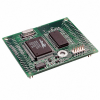
20-101-0404 Rabbit Semiconductor, 20-101-0404 Datasheet - Page 65

20-101-0404
Manufacturer Part Number
20-101-0404
Description
MODULE RABBITCORE RCM2000
Manufacturer
Rabbit Semiconductor
Datasheet
1.20-101-0383.pdf
(80 pages)
Specifications of 20-101-0404
Module/board Type
MPU Core Module
Product
Microcontroller Modules
Core Processor
Rabbit 2000
Clock Speed
25.8 MHz
Interface Type
Ethernet, Serial
Flash
256 KB
Timers
5 x 8 bit, 2 x 10 bit
Operating Supply Voltage
4.75 V to 5.25 V
Board Size
48.3 mm x 58.4 mm x 14 mm
Core
RCM2000
Processor Series
RCM2000
Cpu Core
Rabbit 2000
For Use With/related Products
RCM2000
Lead Free Status / RoHS Status
Lead free / RoHS Compliant
Other names
316-1083
B.4.1 Adding Other Components
There is room on the Prototyping Board for a user-supplied RS-232 transceiver chip at
location U2 and a 10-pin header for serial interfacing to external devices at location J6. A
Maxim MAX232 transceiver is recommended. When adding the MAX232 transceiver at
position U2, you must also add 100 nF charge storage capacitors at positions C3–C6 as
shown in Figure B-7.
Figure B-7. Location for User-Supplied RS-232 Transceiver
and Charge Storage Capacitors
There are two sets of pads that can be used for surface mount prototyping SOIC devices.
The silk screen layout separates the rows into six 16-pin devices (three on each side).
However, there are pads between the silk screen layouts giving the user two 52-pin (2x26)
SOIC layouts with 50 mil pin spacing. There are six sets of pads that can be used for 3- to
6-pin SOT23 packages. There are also 60 sets of pads that can be used for SMT resistors
and capacitors in an 0805 SMT package. Each component has every one of its pin pads
connected to a hole in which a 30 AWG wire can be soldered (standard wire wrap wire can
be soldered in for point-to-point wiring on the Prototyping Board). Because the traces are
very thin, carefully determine which set of holes is connected to which surface mount pad.
User’s Manual
61


