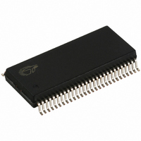
CY7C66113-PVC Cypress Semiconductor Corp, CY7C66113-PVC Datasheet - Page 27

CY7C66113-PVC
Manufacturer Part Number
CY7C66113-PVC
Description
IC MCU 8K USB HUB 4 PORT 56TSSOP
Manufacturer
Cypress Semiconductor Corp
Specifications of CY7C66113-PVC
Applications
USB Hub/Microcontroller
Core Processor
M8
Program Memory Type
OTP (8 kB)
Controller Series
USB Hub
Ram Size
256 x 8
Interface
I²C, USB, HAPI
Number Of I /o
31
Voltage - Supply
4 V ~ 5.5 V
Operating Temperature
0°C ~ 70°C
Mounting Type
Surface Mount
Package / Case
56-SSOP
Operating Temperature (max)
70C
Operating Temperature (min)
0C
Operating Temperature Classification
Commercial
Mounting
Surface Mount
Pin Count
56
Lead Free Status / RoHS Status
Contains lead / RoHS non-compliant
For Use With
CY3649 - PROGRAMMER HI-LO USB M8428-1339 - KIT LOW SPEED PERSONALITY BOARD
Lead Free Status / RoHS Status
Not Compliant, Contains lead / RoHS non-compliant
Other names
428-1330
Available stocks
Company
Part Number
Manufacturer
Quantity
Price
Company:
Part Number:
CY7C66113-PVC
Manufacturer:
CY
Quantity:
10
16.1
The SIE allows the CY7C66xxx microcontroller to communicate with the USB host through the USB repeater portion of the hub.
The SIE simplifies the interface between the microcontroller and USB by incorporating hardware that handles the following USB
bus activity independently of the microcontroller:
Firmware is required to handle the following USB interface tasks:
16.2
The enumeration sequence in a compound device begins with the hub and finishes with the device functions. The hub is enu-
merated first. Then the integrated compound function is enumerated. Then the Hub connection status is read to determine which,
if any, of the downstream ports need to be enumerated. Following is a very brief summary of the enumeration process of a USB
function by the host. For a detailed description of the enumeration process, refer to the latest USB specifications published by
USBIF, or check their web site at www.usb.org.
10.The USB Controller retrieves the descriptors from its program space and returns the data to the host over the USB.
11.Enumeration is complete after the host has received all the descriptors.
17.0
A USB hub is required to support:
These features are mapped onto a hub repeater and a hub controller. The hub controller is supported by the processor integrated
into the CY7C66011/12/13 and CY7C66111/12/13 microcontrollers. The hardware in the hub repeater detects whether a USB
device is connected to a downstream port and the interface speed of the downstream device. The connection to a downstream
port is through a differential signal pair (D+ and D–). Every downstream port provided by the hub requires an external 15-k
resistors from each signal line to ground. The effect is when a device is not present, the hub will read a LOW (zero) on both D+
and D–. This condition, referred to as a single-ended-zero (SE0), can be used to identify the “no connect” state.
17.1
A low-speed (1.5 Mbps) USB device will have a pull-up resistor on the D– pin. At connect time, the bias resistors set the signal
levels on the D+ and D– lines. When a low-speed device is connected to a hub port, the hub will see a LOW on D+ and a HIGH
on D–. This tells the hub repeater that a low-speed device is connected to the port. The hub repeater sets a connect bit in the
Hub Port Connect Status register for the downstream port. The hub repeater also sets a bit in the Hub Port Speed register to
1. The host computer sends a SETUP packet followed by a DATA packet to USB address 0 requesting the Device descriptor.
2. The USB Controller decodes the request and retrieves its Device descriptor from the program memory space.
3. The host computer performs a control read sequence and the USB Controller responds by sending the Device descriptor over
4. After receiving the descriptor, the host computer sends a SETUP packet followed by a DATA packet to address 0 assigning a
5. The USB Controller stores the new address in its USB Device Address Register after the no-data control sequence completes.
6. The host sends a request for the Device descriptor using the new USB address.
7. The USB Controller decodes the request and retrieves the Device descriptor from the program memory.
8. The host performs a control read sequence and the USB Controller responds by sending its Device descriptor over the USB bus.
9. The host generates control reads to the USB Controller to request the Configuration and Report descriptors.
• Bit stuffing/unstuffing
• Checksum generation/checking
• ACK/NAK/STALL
• TOKEN type identification
• Address checking
• Coordinate enumeration by responding to SETUP packets
• Fill and empty the FIFOs
• Suspend/Resume coordination
• Verify and select DATA toggle values
• Connectivity behavior
• Bus fault detection and recovery
• Full-/Low-speed device support
the USB bus.
new USB address to the device.
USB Serial Interface Engine (SIE)
USB Enumeration
Connecting/Disconnecting a USB Device
USB Hub
PRELIMINARY
27
CY7C66011/12/13
CY7C66111/12/13


