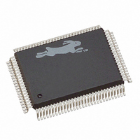
20-668-0003 Rabbit Semiconductor, 20-668-0003 Datasheet - Page 84

20-668-0003
Manufacturer Part Number
20-668-0003
Description
IC CPU RABBIT2000 30MHZ 100PQFP
Manufacturer
Rabbit Semiconductor
Datasheet
1.20-668-0003.pdf
(228 pages)
Specifications of 20-668-0003
Processor Type
Rabbit 2000 8-Bit
Speed
30MHz
Voltage
2.7V, 3V, 3.3V, 5V
Mounting Type
Surface Mount
Package / Case
100-MQFP, 100-PQFP
Data Bus Width
8 bit
Maximum Clock Frequency
30 MHz
Operating Supply Voltage
0 V to 5.5 V
Maximum Operating Temperature
+ 85 C
Mounting Style
SMD/SMT
Minimum Operating Temperature
- 40 C
Number Of Programmable I/os
40
Number Of Timers
8 & 10 bit
Lead Free Status / RoHS Status
Lead free / RoHS Compliant
Features
-
Lead Free Status / Rohs Status
Lead free / RoHS Compliant
Other names
20-668-0003
316-1062
316-1062
Available stocks
Company
Part Number
Manufacturer
Quantity
Price
Company:
Part Number:
20-668-0003
Manufacturer:
Rabbit Semiconductor
Quantity:
10 000
- Current page: 84 of 228
- Download datasheet (2Mb)
7.6 Time/Date Clock (Real-Time Clock)
The time/date clock (RTC) is a 48-bit (ripple) counter that is driven by the 32.768 kHz
oscillator. The RTC is a modified ripple counter composed of six separate 8-bit counters.
The carries are fed into all six 8-bit counters at the same time and then ripple for 8 bits.
The time for this ripple to take place is a few nanoseconds per bit, and certainly should not
should not exceed 200 ns for all 8 bits, even when operating at low voltage.
The 48 bits are enough bits to count up 272 years at the 32 kHz clock frequency. By con-
vention, 12 AM on January 1, 1980, is taken as time zero. Rabbit Semiconductor software
ignores the highest order bit, giving the counter a capacity of 136 years from January 1,
1980. To read the counter value, the value is first transferred to a 6-byte holding register.
Then the individual bytes may be read from the holding registers. To perform the transfer,
any data bits are written to RTC0R, the first holding register. The counter may then be
read as six 8-bit bytes at RTC0R through RTC5R. The counter and the 32 kHz oscillator
are powered from a separate power pin that can be provided with power while the remain-
der of the chip is powered down. This design makes battery backup possible. Since the
processor operates on a different clock than the RTC, there is the possibility of performing
a transfer to the holding registers while a carry is taking place, resulting in incorrect infor-
mation. In order to prevent this, the processor should do the clock read twice and make
sure that the value is the same in both reads.
If the processor is itself operating at 32 kHz, the read-clock procedure must be modified
since a number of clock counts would take place in the time needed by the slow-clocked
processor to read the clock. An appropriate modification would be to ignore the lower
bytes and only read the upper 5 bytes, which are counted once every 256 clocks or every
1/128th of a second. If the read cannot be performed in this time, further low-order bits
can be ignored.
The RTC registers cannot be set by a write operation, but they can be cleared and counted
individually, or by subset. In this manner, any register or the entire 48-bit counter can be
set to any value with no more than 256 steps. If the 32 kHz crystal is not installed and the
input pin is grounded, no counting will take place and the six registers can be used as a
small battery-backed memory. Normally this would not be very productive since the cir-
cuitry needed to provide the power switchover could also be used to battery-back a regular
low-power static RAM.
78
Real-Time Clock x Holding Register
Table 7-5. Real-Time Clock Read Registers
(RTC1R)
(RTC2R)
(RTC3R)
(RTC4R)
(RTC5R)
(RTC0R) R/W
Rabbit 2000 Microprocessor User’s Manual
(Address = 00000100)
(Address = 00000101)
(Address = 00000110)
(Address = 00000111)
(Address = 00000010)
(Address = 00000011)
Related parts for 20-668-0003
Image
Part Number
Description
Manufacturer
Datasheet
Request
R

Part Number:
Description:
IC CPU RABBIT4000 128-LQFP
Manufacturer:
Rabbit Semiconductor
Datasheet:

Part Number:
Description:
IC MPU RABIT3000A 55.5MHZ128LQFP
Manufacturer:
Rabbit Semiconductor
Datasheet:

Part Number:
Description:
Microprocessors - MPU Rabbit 3000 TFBGA Microprocessor
Manufacturer:
Rabbit Semiconductor

Part Number:
Description:
Microprocessors - MPU Rabbit 4000 LQFP Microprocessor
Manufacturer:
Rabbit Semiconductor

Part Number:
Description:
IC, I/O EXPANDER, 8BIT, 40MHZ, TQFP-64
Manufacturer:
Rabbit Semiconductor

Part Number:
Description:
SCRs 1.5A 200uA 400V Sensing
Manufacturer:
Littelfuse Inc
Datasheet:

Part Number:
Description:
CARD 6-RELAY SMARTSTAR SR9500
Manufacturer:
Rabbit Semiconductor
Datasheet:

Part Number:
Description:
WIRE-BOARD CONN RECEPTACLE, 6POS, 3.96MM
Manufacturer:
TE Connectivity
Datasheet:

Part Number:
Description:
ADAPTER 20 PIN .420" PLUGS(6PCS)
Manufacturer:
Logical Systems Inc.
Datasheet:

Part Number:
Description:
CONN BARRIER BLOCK .438" 20 POS
Manufacturer:
Cinch Connectors
Datasheet:

Part Number:
Description:
20 MODII 2PC HDR DR SHRD, ROHS
Manufacturer:
TE Connectivity
Datasheet:

Part Number:
Description:
WIRE-BOARD CONN RECEPTACLE, 6POS, 3.96MM
Manufacturer:
TE Connectivity
Datasheet:


