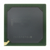
PRIXP425BC Intel, PRIXP425BC Datasheet - Page 25

PRIXP425BC
Manufacturer Part Number
PRIXP425BC
Description
IC NETWRK PROCESSR 400MHZ 492BGA
Manufacturer
Intel
Specifications of PRIXP425BC
Processor Type
Network
Features
XScale Core
Speed
400MHz
Voltage
1.3V
Mounting Type
Surface Mount
Package / Case
492-BGA
Core Operating Frequency
400MHz
Package Type
BGA
Pin Count
492
Mounting
Surface Mount
Operating Temperature (max)
70C
Operating Temperature (min)
0C
Operating Temperature Classification
Commercial
Lead Free Status / RoHS Status
Lead free / RoHS Compliant
Other names
869083
Available stocks
Company
Part Number
Manufacturer
Quantity
Price
Part Number:
PRIXP425BC
Manufacturer:
INTEL
Quantity:
20 000
Implication:
Workaround:
Status:
20.
Problem:
Implication:
Workaround:
Status:
21.
Problem:
Implication:
Workaround:
Status:
22.
Problem:
Implication:
Intel
®
IXP42X Product Line of Network Processors and IXC1100 Control Plane Processor
The expansion bus will not extend the T3 data state as shown in Figure 60 of the Intel
Product Line of Network Processors and IXC1100 Control Plane Processor Developer’s Manual
(252480-002).
To avoid unexpected timing issues, T2 or T3 need to be programmed to non-zero values and
assurances made that EX_IOWAIT_N is asserted at least three cycles before the deasserting edge
of EX_RD_N. Additionally, the extended wait states will not be changed after the deassertion of
EX_IOWAIT_N
No
SOF During Control Read Can Corrupt USB Transfer (SCR 1553)
An SOF packet sent in between the setup and data stage of a control read transfer is decoded as an
OUT token by the UDC core. This causes the command state machine to prematurely transit to the
status stage.
When a USB host issues an IN token for the data stage, the UDC responds with a null data packet
instead of the requested data bytes. This is because the UDC core has transitioned to status stage
and assumes that this is a status in transaction.
None.
Fixed.
USB - Invalid 0x81 Value in Endpoint 0 Control Register on SETUP Transfer
(SCR 3077)
After the status-OUT stage of an USB standard Control Read Command, such as
GET_DESCRIPTOR, GET_INTERFACE, and GET_STATUS, if the UDCCS0(OPR) is not
cleared by the users before the next SETUP packet is received, then the UDCCS0 could contain an
invalid value.
The invalid value is UDCCS0 = 0x81, which indicates that a SETUP packet was received, but the
UDDR0 Data FIFO is empty, however, the SETUP packet data is actually in the UDDR0 Data
FIFO.
Software can get confused if the status register indicates that a SETUP packet was received
(UDCCS0[SA]=1), an OUT packet is ready (UDCCS0[OPR]=1), but the UDDR0 Data FIFO is
empty (UDCCS0[RNE]=0).
Software should treat UDCCS0 = 0x81 as a valid value and read 8 bytes from the UDDR0 Data
FIFO while ignoring UDCCS0[RNE]. This 8 bytes of data will be the correct data from the SETUP
Command.
No
Ethernet Coprocessors - Ethernet Pad Enable Overrides Append FCS
(SCR 299)
The IXP42X product line and IXC1100 control plane processors have an Ethernet Coprocessor that
is configured by Intel XScale core software. [Note that some IXP42X product line and IXC1100
control plane processors have two Ethernet Coprocessors.] The Coprocessor can be programmed
via the Ethernet Transmit Control Registers to either append or not append the FCS on the
transmitted Ethernet frames. When the frame payload size is less than 60 bytes, the Pad Enable
control bit has priority over the Append FCS control bit on whether or not the FCS is appended on
a frame.
When the frame payload size is less than 60 bytes, the FCS will be appended to the Transmit
frames even though the Append FCS control bit is NOT set because the Pad Enable control bit
overrides the Append FCS control bit.
Fix.
Fix.
.
Non-Core Errata
®
IXP42X
25


