412K-12 TELEDYNE, 412K-12 Datasheet
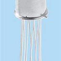
RF (Radio Frequency) Relays DPDT HIGH SHOCK RELAY - 12V

412K-12

Manufacturer Part Number
412K-12
Description
RF (Radio Frequency) Relays DPDT HIGH SHOCK RELAY - 12V
Manufacturer
TELEDYNE
Datasheet
©2003 TELEDYNE RELAYS
Temperature (Ambient)
Vibration (General Note 1)
Shock
Acceleration
Enclosure
Weight
Temperature (Ambient)
Vibration (General Note 1)
Shock
Acceleration
Enclosure
Weight
UNI-FRAME
ARMATURE
INTERNAL CONSTRUCTION
412K ENVIRONMENTAL AND
PHYSICAL SPECIFICATIONS
422K ENVIRONMENTAL AND
PHYSICAL SPECIFICATIONS
(General
Note 1)
(General
Note 4)
(General
Note 1)
(General
Note 4)
DESIGNATION
SERIES
412K
422K
–65°C to +125°C
30 g’s to 3000 Hz
75 g’s, 6 msec, half-sine
4000 g’s, 0.5 msec. axial
plane, half-sine
1000 g’s, 0.5 msec side
planes, half-sine
50 g’s
Hermetically sealed
0.09 oz. (2.55g) max.
–65°C to +125°C
30 g’s to 3000 Hz
100 g’s, 6 msec, half-sine
2100 g’s, 0.5 msec. axial
plane, half-sine
750 g’s, 0.5 msec side
planes, half-sine
50 g’s
Hermetically sealed
0.10 oz. (2.84g) max.
CONTACT
MOVING
STATIONARY
SPECIFICATIONS ARE SUBJECT TO CHANGE WITHOUT NOTICE
STATIONARY
CONTACT
CONTACT
UPPER
LOWER
DPDT high-shock relay
DPDT high-shock magnetic-latching relay
HIGH-PERFORMANCE
DESCRIPTION
The TO-5 relay, originally conceived and developed by Teledyne, has become one of the
industry standards for low-level switching from dry circuit to 1 ampere. Designed for high-
density PC board mounting, its small size and low coil power dissipation make the TO-5
relay one of the most versatile subminiature relays available.
The K Series high-shock TO-5 relays are designed to withstand shock levels up to 4000
g’s, .5 millisecond duration. Special material selection and construction details provide
assurance that critical elements of the relay structure and mechanism will not be
permanently displaced or damaged as a result of extremely high g level shocks.
Typical applications:
• Commercial avionics aircraft control
• Commercial aircraft control systems
• Transportation systems (rail/truck)
By virtue of their inherently low intercontact capacitance and contact circuit losses, the
K Series relays have proven to be excellent subminiature RF switches for applications
with frequency ranges well into the UHF spectrum. A typical RF application for the TO-5
relay is in handheld radio transceivers, wherein the combined features of good RF
performance, small size, low coil power dissipation and high reliability make it a
preferred method of T-R switching (see Figure 1 and 2).
PRINCIPLE OF OPERATION 422K
Energizing Coil B produces a magnetic field
opposing the holding flux of the permanent magnet
in Circuit B. As this net holding force decreases, the
attractive force in the air gap of circuit A, which also
results from the flux of the permanent magnet,
becomes great enough to break the armature free of
Core B, and snap it into a closed position against
Core A. The armature then remains in this position
upon removal of power from Coil B, but will snap
back to position B upon energizing Coil A. Since operation depends upon cancellation
of a magnetic field, it is necessary to apply the correct polarity to the relay coils as
indicated on the relay schematic.
When latching relays are installed in equipment, the latch and reset coils should not be
pulsed simultaneously. Coils should not be pulsed with less than rated coil voltage and
the pulse width should be a minimum of three times the specified operate time of the
relay. If these conditions are not followed it is possible for the relay to be in the
magnetically neutral position.
HIGH-SHOCK,
www.teledynerelays.com
TO-5 RELAY
DPDT
RELAY TYPE
MAGNETIC CIRCUIT B
SOFT IRON
SOFT IRON
ARMATURE
CORE B
COIL B
PERMANENT MAGNET
SERIES
412K
422K
412K/422K Page 1
412K/422K/1203/Q1
MAGNETIC CIRCUIT A
SOFT IRON FRAME
MOVING
CONTACT
COIL A
SOFT IRON
CORE A
AIR GAP
STATIONARY
CONTACT

Related parts for 412K-12

412K-12 Summary of contents

Page 1

... If these conditions are not followed it is possible for the relay the magnetically neutral position. www.teledynerelays.com SERIES 412K 422K PERMANENT MAGNET MAGNETIC CIRCUIT A MAGNETIC CIRCUIT B SOFT IRON FRAME COIL A COIL B SOFT IRON SOFT IRON CORE A CORE B AIR GAP SOFT IRON ARMATURE STATIONARY CONTACT MOVING CONTACT 412K/422K Page 1 412K/422K/1203/Q1 ...

Page 2

... Nom. 5.0 6.0 Max. 5.8 8.0 61 120 3.5 4.5 www.teledynerelays.com } measured 1/8" below header 70,000 ft.: 125 Vrms/60Hz 412K-9 412K-12 412K-18 412K-26 9.0 12.0 18.0 26.5 12.0 16.0 24.0 32.0 160 300 600 1350 7.6 10.0 14.3 21.0 ...

Page 3

... Survival only — contact chatter may occur. COIL A www.teledynerelays.com TYPICAL RF PERFORMANCE 1.92 20 1.22 30 1.07 40 1.02 50 1.01 60 1.00 70 1.00 .01 0 1.0 FREQUENCY (GHz) FIGURE 2 (422K) 0.9 1.0 .031 (0.79) ± .003 (0.08 36° ±3° TYP. 422K DIMENSIONS ARE SHOWN IN INCHES (MILLIMETERS) 412K/422K Page 3 412K/422K/1203/Q1 ...

Page 4

... Dimensions are in inches (mm). 4. Unless otherwise speci¿ ed, tolerance is ± .010 (.25). 5. Add the contact resistance show in the datasheet. 6. Add 0.01 oz. (0. the weight of the relay assembly shown in the datasheet. © 2008 Teledyne Relays Appendix A: Spacer Pads Height For use with the following: ...

Page 5

... Dim H MAX .014 [0.36] (REF) .370 [9.4] MIN +44 (0) 1236 453124 • www.teledyne-europe.com For use with the following: ER411T, J411T, ER412, ER412D ER412DD, J412, J412D, J412DD ER412T, J412T 712, 712D, 712TN ER431T, J431T, ER432, ER432D ER432DD, J432, J432D, J432DD ER432T, J432T ...

Page 6

... Centigrid® Relays: RF180, ER116C, 122C, ER136C Indicates ground pin position Indicates glass insulated lead position Indicates ground pin or lead position depending on relay type © 2008 Teledyne Relays "Z" POSITION "X" POSITION "Y" POSITION TO-5 Relays: ER411, ER431, RF311, RF331 " ...

Related keywords