MB2411E1G13-RO NKK Switches, MB2411E1G13-RO Datasheet - Page 4
MB2411E1G13-RO
Manufacturer Part Number
MB2411E1G13-RO
Description
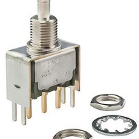
Pushbutton Switches ON-(ON) .4VA 1/4 D-FLAT BSHNG BRKT PC
Manufacturer
NKK Switches
Series
MB2400r
Type
Snap-Action Bracket PC Mount Pushbuttonsr
Datasheet
1.MB2411A2W13.pdf
(8 pages)
Specifications of MB2411E1G13-RO
Contact Form
SPDT
Switch Function
ON - (ON)
Contact Rating
0.4 Volt-Amp at 28 VoltsAC/DC
Termination Style
Straight PC, 6.35 mm with 11.8 mm Bracket
Actuator
Plunger, without Cap
Supply Voltage
28 VoltsAC/DC
Mounting Style
Through Hole
Terminal Seal
Epoxy
Contact Plating
Gold
Contact Material
Copper
Illumination
Not Illuminated
Flammability Rating
UL 94 V-0
Dielectric Strength
1000 VoltsAC
Features
Snap-acting mechanism gives smooth actuation
Housing Material
Diallyl Phthalate Resin
Insulation Resistance
1000 MOhms
Mounting Angle
Straight
Operating Force
2.45 N
Lead Free Status / Rohs Status
Lead free / RoHS Compliant
Other names
633-MB2411E1G13 MB-2411-N310 MB2411E1G13


Snap-Action Bracket PC Mount Pushbuttons
Pole
DP
(8.0) Dia
.315
SP
Standard Hardware: .068” (1.74mm)
(8.0) Dia
.315
A2
A1
Maximum Panel Thickness with
.031
For A1, A2, S1, or S2 Bushing
(0.8)
(0.8)
.031
*MB2411
MB2461
.280” (7.1mm)
Smooth with Keyway
.280” (7.1mm)
Threaded with Keyway
Model
(6.5) Dia
.256
with Keyway
.098
(2.5)
.098
(2.5)
(2.84) Dia
.112
(2.84) Dia
.112
.024
(0.6)
Normal
1/4-40 Thd
(5.54)
(6.2) Dia
.244
.218
(5.54)
.220
ON
ON
.218
(5.6)
( ) = Momentary
Plunger Position
Keyway
Hardware is illustrated following the Typical Switch Dimension drawings.
.280
(7.1)
.280
(7.1)
Note: Plunger selection is not required for MB2400 pushbuttons.
.035
(0.9)
.035
(0.9)
Standard hardware includes 2 hex nuts & 1 lockwasher.
Down
(ON)
(ON)
The plunger can be used with or without a cap.
(8.0) Dia
.315
(8.0) Dia
.315
E2
E1
Standard Hardware: .068” (1.74mm)
Maximum Panel Thickness with
POLES & CIRCUITS
.285” (7.24mm)
Smooth with D Flat
.285” (7.24mm)
Threaded with D Flat
For E1 or E2 Bushing
(6.5) Dia
.256
1-3 4-6
Normal
BUSHINGS
Panel Cutouts
Connected Terminals
1-3
with D Flat
Keyway
.098
.098
(2.5)
(2.5)
www.nkk.com
(2.84) Dia
(2.84) Dia
.112
.112
1/4-40 Thd
.244
(5.54)
(5.54)
(6.2) Dia
.218
.218
(5.8)
.228
1-2 4-5
(7.24)
.285
(7.24)
Down
.285
1-2
.035
.035
(0.9)
(0.9)
Note: Terminal numbers are not actually
*
SPDT
DPDT
When using terminal code 32, connected
terminals and schematic are reversed.
Series MB2400
(8.0) Dia
.315
(8.0) Dia
.315
Standard Hardware: .134” (3.40mm)
S2
S1
Throw & Switch Schematics
on the switch.
.031
Maximum Panel Thickness with
(0.8)
.031
(0.8)
Optional Locking Ring
.350” (8.9mm)
Smooth with Keyway
.350” (8.9mm)
Threaded with Keyway
3
(6.5) Dia
.256
(2.2) Dia
.087
3
1
.098
(2.5)
.098
(2.5)
(COM)
With
2
(2.84) Dia
(2.84) Dia
1
.112
.112
6
(COM)
1/4-40 Thd
2
4
.244
(5.54)
(6.2) Dia
(5.54)
(6.5)
.256
.218
.218
.350
.350
(8.9)
(8.9)
5
C103
.035
(0.9)
.035
(0.9)
C
Related parts for MB2411E1G13-RO
Image
Part Number
Description
Manufacturer
Datasheet
Request
R

Part Number:
Description:
Rocker Switches & Paddle Switches High In-rush Rated Rocker Switch
Manufacturer:
NKK Switches
Datasheet:
Part Number:
Description:
Rocker Switches & Paddle Switches High In-rush Rated Rocker Switch
Manufacturer:
NKK Switches
Datasheet:
Part Number:
Description:
Rocker Switches & Paddle Switches High In-rush Rated Rocker Switch
Manufacturer:
NKK Switches
Datasheet:
Part Number:
Description:
Rocker Switches & Paddle Switches High In-rush Rated Rocker Switch
Manufacturer:
NKK Switches
Datasheet:

Part Number:
Description:
Pushbutton Switches SPST ON(OFF) 15/32'
Manufacturer:
NKK Switches
Datasheet:

Part Number:
Description:
Pushbutton Switches SPST OFF(ON) 15/32'
Manufacturer:
NKK Switches
Datasheet:

Part Number:
Description:
Pushbutton Switches ON(OFF) NORM CLSD 3A RED PLNGR LUG 15/32
Manufacturer:
NKK Switches
Datasheet:

Part Number:
Description:
Pushbutton Switches SPDT ON-(ON)
Manufacturer:
NKK Switches
Datasheet:

Part Number:
Description:
Pushbutton Switches ON-(ON) RND BUSH MNT RED LED RED/RED CAP
Manufacturer:
NKK Switches
Datasheet:
Part Number:
Description:
Pushbutton Switches SPST ON-(OFF) STRT
Manufacturer:
NKK Switches
Datasheet:
Part Number:
Description:
Pushbutton Switches OFF(ON) NORM OPEN 3A RED CAP LUG 15/32
Manufacturer:
NKK Switches
Datasheet:
Part Number:
Description:
Pushbutton Switches ILLUM PUSHBUTTON SPDT
Manufacturer:
NKK Switches
Datasheet:
Part Number:
Description:
Pushbutton Switches OFF(ON) NORM OPEN 3A BLK CAP LUG 15/32
Manufacturer:
NKK Switches
Datasheet:
Part Number:
Description:
Pushbutton Switches SPST NO Metric Thrd Blk Plunge w/Blu Cap
Manufacturer:
NKK Switches
Datasheet:
Part Number:
Description:
Pushbutton Switches SPST OFF-(ON) NO 3A
Manufacturer:
NKK Switches
Datasheet: