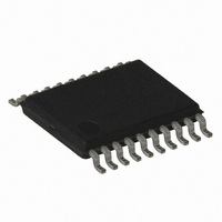
ATF16V8C-7XC Atmel, ATF16V8C-7XC Datasheet - Page 6

ATF16V8C-7XC
Manufacturer Part Number
ATF16V8C-7XC
Description
IC PLD 7NS 20TSSOP
Manufacturer
Atmel
Datasheet
1.ATF16V8C-7PU.pdf
(23 pages)
Specifications of ATF16V8C-7XC
Programmable Type
EE PLD
Number Of Macrocells
8
Voltage - Input
5V
Speed
7ns
Mounting Type
Surface Mount
Package / Case
20-TSSOP
Lead Free Status / RoHS Status
Contains lead / RoHS non-compliant
Other names
ATF16V8C7XC
7.
9.
10.
6
Power-up reset
Registers of the ATF16V8C are designed to reset during power-up. At a point delayed slightly from V
registers will be reset to the low state. As a result, the registered output state will always be high on power-up.
This feature is critical for state machine initialization. However, due to the asynchronous nature of reset and the uncertainty
of how V
Figure 8.
Table 8-1.
Power-down mode
The ATF16V8C includes an optional pin controlled powerdown feature. Device pin 4 may be configured as the power-
down pin. When this feature is enabled and the power-down pin is high, total current consumption drops to less than
100μA. In the power-down mode, all output data and internal logic states are latched and held. All registered and
combinatorial output data remains valid. Any outputs that were in a high-Z state at the onset of power-down will remain at
high-Z. During power-down, all input signals except the power-down pin are blocked. The input and I/O pin-keeper circuits
remain active to insure that pins do not float to indeterminate levels. This helps to further reduce system power.
Selection of the power-down option is specified in the ATF16V8C logic design file. The logic compiler will include this option
selection in the otherwise standard 16V8 JEDEC fuse file. When the power-down feature is not specified in the design file,
pin 4 is available as a logic input, and there is no power-down pin. This allows the ATF16V8C to be programmed using any
existing standard 16V8 fuse file.
Note:
Registered output preload
Registers of the ATF16V8C are provided with circuitry to allow loading of each register with either a high or a low. This
feature will simplify testing since any state can be forced into the registers to control test sequencing. A JEDEC file with
preload is generated when a source file with vectors is compiled. Once downloaded, the JEDEC file preload sequence will
be done automatically by approved programmers.
Parameter
t
V
1.
2.
3.
Atmel ATF16V8C
PR
RST
The V
After reset occurs, all input and feedback setup times must be met before driving the clock term high, and
The signals from which the clock is derived must remain stable during t
Some programmers list the JEDEC-compatible 16V8C (No PD used) separately from the non-JEDEC compatible 16V8CEXT.
(EXT for extended features.)
CC
actually rises in the system, the following conditions are required:
CC
Power-up reset parameters
Power-up reset
rise must be monotonic, from below 0.7V
Description
Power-up
Power-up
Reset Time
Reset Voltage
600
Typ
3.8
1,000
Max
4.5
Units
ns
V
PR
CC
crossing V
0425H–PLD–3/11
RST
, all


