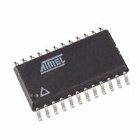
ATF22V10C-15SI Atmel, ATF22V10C-15SI Datasheet - Page 8

ATF22V10C-15SI
Manufacturer Part Number
ATF22V10C-15SI
Description
IC PLD EE HP 15NS 24-SOIC
Manufacturer
Atmel
Specifications of ATF22V10C-15SI
Programmable Type
EE PLD
Number Of Macrocells
10
Voltage - Input
5V
Speed
15ns
Mounting Type
Surface Mount
Package / Case
24-SOIC (7.5mm Width)
Family Name
ATF22V10C
Process Technology
EECMOS
# Macrocells
10
# I/os (max)
10
Frequency (max)
83.3MHz
Propagation Delay Time
15ns
Operating Supply Voltage (typ)
5V
Operating Supply Voltage (min)
4.5V
Operating Supply Voltage (max)
5.5V
Supply Current
115mA
Operating Temp Range
-40C to 85C
Operating Temperature Classification
Industrial
Mounting
Surface Mount
Pin Count
24
Package Type
SOIC
Lead Free Status / RoHS Status
Contains lead / RoHS non-compliant
Available stocks
Company
Part Number
Manufacturer
Quantity
Price
Company:
Part Number:
ATF22V10C-15SI
Manufacturer:
ATMEL
Quantity:
23
Part Number:
ATF22V10C-15SI
Manufacturer:
AIMEL
Quantity:
20 000
7. Programming/Erasing
8. Input and I/O Pin-keeper Circuits
8
ATF22V10C(Q)
Programming/erasing is performed using standard PLD programmers. See “CMOS PLD Pro-
gramming Hardware & Software Support” for information on software/programming.
Table 7-1.
The ATF22V10C contains internal input and I/O pin-keeper circuits. These circuits allow each
ATF22V10C pin to hold its previous value even when it is not being driven by an external source
or by the device’s output buffer. This helps to ensure that all logic array inputs are at known valid
logic levels. This reduces system power by preventing pins from floating to indeterminate levels.
By using pin-keeper circuits rather than pull-up resistors, there is no DC current required to hold
the pins in either logic state (high or low).
These pin-keeper circuits are implemented as weak feedback inverters, as shown in the Input
Diagram below. These keeper circuits can easily be overdriven by standard TTL- or CMOS-com-
patible drivers. The typical overdrive current required is 40 µA.
Figure 8-1.
Parameter
t
V
PR
RST
Programming/Erasing
Input Diagram
Description
Power-up Reset Time
Power-up Reset Voltage
Typ
600
3.8
1,000
Max
4.5
0735S–PLD–8/08
Units
ns
V


