USB2512AI-AEZG SMSC, USB2512AI-AEZG Datasheet - Page 69
USB2512AI-AEZG
Manufacturer Part Number
USB2512AI-AEZG
Description
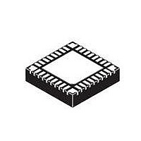
IC CTRLR USB2.0 2PORT 36QFN
Manufacturer
SMSC
Type
USB HUB Controllerr
Specifications of USB2512AI-AEZG
Controller Type
USB 2.0 Controller
Interface
Serial EEPROM
Voltage - Supply
3 V ~ 3.6 V
Current - Supply
95mA
Operating Temperature
-40°C ~ 85°C
Mounting Type
Surface Mount
Package / Case
36-QFN
Operating Supply Voltage
3.3 V
Maximum Operating Temperature
+ 85 C
Minimum Operating Temperature
- 40 C
Mounting Style
SMD/SMT
Operating Temperature Range
- 40 C to + 85 C
Supply Current
90 mA
For Use With
638-1041 - BOARD EVAL FOR USB2512/USB2512I
Lead Free Status / Rohs Status
Lead free / RoHS Compliant
Other names
638-1089
Available stocks
Company
Part Number
Manufacturer
Quantity
Price
Company:

Part Number:
USB2512AI-AEZG
Manufacturer:
Standard
Quantity:
2 736
Company:
Part Number:
USB2512AI-AEZG
Manufacturer:
SMSC
Quantity:
4 450
Part Number:
USB2512AI-AEZG
Manufacturer:
SMSC
Quantity:
20 000


USB 2.0 Hi-Speed Hub Controller
Datasheet
Chapter 10 AC Specifications
SMSC USB251x
10.1
1.Only when SEL48 is available and supported.
C
C
C
C
C
C
C
SYMBOL
0
L
B
S
XTAL
1
2
C
C
Crystal: Parallel Resonant, Fundamental Mode, 24/48
External Clock: 50% Duty cycle ± 10%, 24/48 MHz ± 350 ppm, Jitter < 100 ps rms.
Note 10.1 C
Note 10.2 Each of these capacitance values is typically approximately 18 pF.
Oscillator/Crystal
2
1
Crystal shunt capacitance
Crystal load capacitance
Total board or trace
capacitance
Stray capacitance
XTAL pin input capacitance
Load capacitors installed on
OEM board
C
and should be set to ‘0’ for use in the calculation of the capacitance formulas in
Figure 10.2, "Formula to Find the Value of C1 and
present a parasitic capacitance between XTALIN and XTALOUT. For an accurate
calculation of C
XTALOUT into account.
0
0
DESCRIPTION
is usually included (subtracted by the crystal manufacturer) in the specification for C
Figure 10.2 Formula to Find the Value of C
Crystal
Figure 10.1 Typical Crystal Circuit
C
Table 10.1 Crystal Circuit Legend
C
1
1
2
= 2 x (C
and C
= 2 x (C
C
L
2
DATASHEET
, take the parasitic capacitance between traces XTALIN and
Crystal manufacturer’s specification (See
OEM board design
SMSC IC and OEM board design
SMSC IC
Calculated values based on
to Find the Value of C1 and C2"
69
L
L
– C
– C
1 M
0
0
) – C
) – C
IN ACCORDANCE WITH
1
MHz ±350 ppm.
S1
S2
1
C2". However, the OEM PCB itself may
XTAL1
(C
XTAL2
(C
and C
S1 =
S2 =
Figure 10.2, "Formula
2
C
C
(See
B2
B1
+ C
+ C
Note
Note
Revision 1.1 (04-26-10)
XTAL2
XTAL1
10.2)
10.1)
)
)
L
Related parts for USB2512AI-AEZG
Image
Part Number
Description
Manufacturer
Datasheet
Request
R

Part Number:
Description:
Manufacturer:
Standard Microsystems (SMSC)
Datasheet:

Part Number:
Description:
FAST ETHERNET PHYSICAL LAYER DEVICE
Manufacturer:
SMSC Corporation
Datasheet:
Part Number:
Description:
357-036-542-201 CARDEDGE 36POS DL .156 BLK LOPRO
Manufacturer:
SMSC Corporation
Datasheet:
Part Number:
Description:
357-036-542-201 CARDEDGE 36POS DL .156 BLK LOPRO
Manufacturer:
SMSC Corporation
Datasheet:
Part Number:
Description:
357-036-542-201 CARDEDGE 36POS DL .156 BLK LOPRO
Manufacturer:
SMSC Corporation
Datasheet:
Part Number:
Description:
4-PORT USB2.0 HUB CONTROLLER
Manufacturer:
SMSC Corporation
Datasheet:
Part Number:
Description:
Manufacturer:
SMSC Corporation
Datasheet:
Part Number:
Description:
Manufacturer:
SMSC Corporation
Datasheet:
Part Number:
Description:
FDC37C672ENHANCED SUPER I/O CONTROLLER WITH FAST IR
Manufacturer:
SMSC Corporation
Datasheet:
Part Number:
Description:
COM90C66LJPARCNET Controller/Transceiver with AT Interface and On-Chip RAM
Manufacturer:
SMSC Corporation
Datasheet:
Part Number:
Description:
Manufacturer:
SMSC Corporation
Datasheet:
Part Number:
Description:
Manufacturer:
SMSC Corporation
Datasheet:
Part Number:
Description:
Manufacturer:
SMSC Corporation
Datasheet:
Part Number:
Description:
Manufacturer:
SMSC Corporation
Datasheet: