AXA010A0M3Z Lineage Power, AXA010A0M3Z Datasheet
AXA010A0M3Z
Specifications of AXA010A0M3Z


Related parts for AXA010A0M3Z

AXA010A0M3Z Summary of contents
Page 1
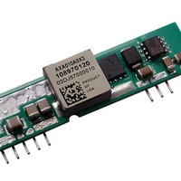
Data Sheet September 30, 2009 Austin Lynx 10 – 14Vdc input; 1.2Vdc to 5.5Vdc Output; 10A Output Current RoHS Compliant Applications Distributed power architectures Intermediate bus voltage applications Telecommunications equipment Servers and storage applications Networking equipment Description TM Austin Lynx ...
Page 2
Data Sheet March 29, 2006 10 – 14Vdc input; 1.2Vdc to 5.5Vdc Output; 10A output current Absolute Maximum Ratings Stresses in excess of the absolute maximum ratings can cause permanent damage to the device. These are absolute stress ratings only, ...
Page 3
Data Sheet March 29, 2006 10 – 14 Vdc input; 1.2Vdc to 5.5Vdc Output; 10A output current Electrical Specifications (continued) Parameter Output Voltage Set-point ( =25°C) IN IN, min O O, max A Output ...
Page 4
Data Sheet March 29, 2006 10 – 14Vdc input; 1.2Vdc to 5.5Vdc Output; 10A output current Electrical Specifications (continued) Parameter Dynamic Load Response (dIo/dt=2.5A/μ =25°C) IN IN, nom A Load Change from Io= 50% ...
Page 5
Data Sheet March 29, 2006 10 – 14 Vdc input; 1.2Vdc to 5.5Vdc Output; 10A output current Feature Specifications Unless otherwise indicated, specifications apply over all operating input voltage, resistive load, and temperature conditions. See Feature Descriptions for additional information. ...
Page 6
Data Sheet March 29, 2006 10 – 14Vdc input; 1.2Vdc to 5.5Vdc Output; 10A output current Characteristic Curves The following figures provide typical characteristics for the Austin Lynx ...
Page 7
Data Sheet March 29, 2006 10 – 14 Vdc input; 1.2Vdc to 5.5Vdc Output; 10A output current Characteristic Curves (continued) The following figures provide typical characteristics for the Austin Lynx ...
Page 8
Data Sheet March 29, 2006 10 – 14Vdc input; 1.2Vdc to 5.5Vdc Output; 10A output current Characteristic Curves (continued) The following figures provide typical characteristics for the Austin Lynx TIME, t (10μs/div) Figure 13. Transient Response to Dynamic Load Change ...
Page 9
Data Sheet March 29, 2006 10 – 14 Vdc input; 1.2Vdc to 5.5Vdc Output; 10A output current Characteristic Curves (continued) The following figures provide thermal derating curves for the Austin Lynx ...
Page 10
Data Sheet March 29, 2006 10 – 14Vdc input; 1.2Vdc to 5.5Vdc Output; 10A output current Test Configurations TO OSCILLOSCOPE L TEST 1μ 1000μF S Electrolytic 2x100μF E.S.R.<0.1Ω Tantalum @ 20°C 100kHz NOTE: Measure input reflected ripple ...
Page 11
Data Sheet March 29, 2006 10 – 14 Vdc input; 1.2Vdc to 5.5Vdc Output; 10A output current Design Considerations (continued) Output Filtering TM The Austin Lynx 12 V SIP module is designed for low output ripple voltage and will meet ...
Page 12
Data Sheet March 29, 2006 10 – 14Vdc input; 1.2Vdc to 5.5Vdc Output; 10A output current Feature Description Remote On/Off TM The Austin Lynx 12V SIP power modules feature an On/Off pin for remote On/Off operation. If not using the ...
Page 13
Data Sheet March 29, 2006 10 – 14 Vdc input; 1.2Vdc to 5.5Vdc Output; 10A output current Feature Descriptions (continued) V (+) V (+) IN O ON/OFF TRIM GND Figure 29. Circuit configuration to trim-down output voltage using an external ...
Page 14
Data Sheet March 29, 2006 10 – 14Vdc input; 1.2Vdc to 5.5Vdc Output; 10A output current Thermal Considerations Power modules operate in a variety of thermal environments; however, sufficient cooling should always be provided to help ensure reliable operation. Considerations ...
Page 15
Data Sheet March 29, 2006 10 – 14 Vdc input; 1.2Vdc to 5.5Vdc Output; 10A output current Mechanical Outline Dimensions are in inches and (millimeters). Tolerances: x.xx in. ± 0.02 in. (x.x mm ± 0.5 mm) [unless otherwise indicated] x.xxx ...
Page 16
Data Sheet March 29, 2006 10 – 14Vdc input; 1.2Vdc to 5.5Vdc Output; 10A output current Recommended Pad Layout Dimensions are in inches and (millimeters). Tolerances: x.xx in. ± 0.02 in. (x.x mm ± 0.5 mm) [unless otherwise indicated] x.xxx ...
Page 17
... C. For Pb solder, the recommended pot temperature is 260 ° C, while the Pb-free solder pot is 270 ° C max. Not all RoHS-compliant through-hole products can be processed with paste-through-hole Pb or Pb-free reflow process. If additional information is needed, please consult with your Lineage Power technical representative for more details. LINEAGE POWER TM ...
Page 18
... AXA010A0M3 10 – 14Vdc AXA010A0Y3 10 – 14Vdc AXA010A0G3 10 – 14Vdc AXA010A0F3 10– 14Vdc AXA010A0A3 10 – 14Vdc AXA010A0P3Z 10 – 14Vdc AXA010A0M3Z 10 – 14Vdc AXA010A0Y3Z 10 – 14Vdc AXA010A0G3Z 10 – 14Vdc AXA010A0F3Z 10– 14Vdc AXA010A0A3Z 10 – 14Vdc -Z refers to RoHS-compliant versions World Wide Headquarters Lineage Power Corporation ...