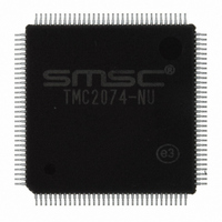
TMC2074-NU SMSC, TMC2074-NU Datasheet - Page 108

TMC2074-NU
Manufacturer Part Number
TMC2074-NU
Description
IC CTRL CIRC 128VTQFP PERIPH MOD
Manufacturer
SMSC
Series
CircLink™r
Datasheet
1.TMC2074-NU.pdf
(116 pages)
Specifications of TMC2074-NU
Controller Type
I/O Controller
Interface
Transceiver
Voltage - Supply
3 V ~ 3.6 V
Current - Supply
40mA
Operating Temperature
0°C ~ 70°C
Mounting Type
Surface Mount
Package / Case
128-TQFP, 128-VQFP
Lead Free Status / RoHS Status
Lead free / RoHS Compliant
Other names
638-1024
Available stocks
Company
Part Number
Manufacturer
Quantity
Price
Company:
Part Number:
TMC2074-NU
Manufacturer:
SMSC
Quantity:
897
Company:
Part Number:
TMC2074-NU
Manufacturer:
Microchip Technology
Quantity:
10 000
Part Number:
TMC2074-NU
Manufacturer:
SMSC
Quantity:
20 000
Part Number:
TMC2074-NU-E3
Manufacturer:
SMSC
Quantity:
20 000
A-6 Details Regarding Reception
Revision 0.2 (10-23-08)
0101010101010101010111111111111111111111
Ending “0”
Reception Data Analysis
Reception data is sampled one bit at a time by an 8 CLK analysis function, and is entered into the SHIFTD
32-bit Shift register. Normally, this is a data bit 1 process in Shift register bit 8. Because jitter is contained
in the actual reception data, synchronization is achieved.
Starting Reception
Reception data is set in accordance with the ARCNET Controller: Various messages start with a bit “1”
sequence (ALERT), and no data exists on the line prior to the first bit “1”. Because the output of the
reception comparator in non-dataflow (Non-Driving period) within a message is unstable, those changes
are warded off in Wait 10 and Wait 01. Afterwards, reception is started when the Alert starting pattern is
detected. Because the first bit “1” in Alert Reception is set, the start symbol is 01100110 and 1
RxStart point.
Recovery
If the Symbol is 11 or 00, data is “1”, and if the Symbol is 01, data is “0”. This output is sequencer output,
and reflects the sequencer state. Data length is set to a standard of 8 CLK, but this can be expanded or
contracted by ± 2 CLK for synchronization purposes.
Error Correction
If symbols not occurring in the CMI transition diagram are received, they will be read as the nearest
matching symbol. For example, if symbol 10 not present in the CMI is received, it is read as either symbol
11 or symbol 00, which will trigger an error. If Symbol 11 were received immediately before, it will be
corrected to 00, because 11 cannot be repeated in the sequence. Conversely, if 00 is received immediately
before, it is corrected to 11. However, if a repeated sequence of 11 is received immediately after receiving
symbol 11, or if a repeated sequence of 00 is received immediately after symbol 00, it is corrected to 01.
Ending
In ACRNET, a “0” ending is attached in final bit 9 of message transmissions. The ARCNET “0” is non-
dataflow 0 and has no function. However, in the CMI, this “0” is active data, flowed as “0” in symbol 01.
Due to this, the “0” ending expected by the ARCNET controller is transmitted as CMI code. However,
because the CMI code bit “0” is displayed in symbol 01, what follows the final bit “0” retains the same state
and the symbol becomes “0111111....”. It is then read at the receiving end as bit “010*0*...” (0* is the result
of misreading 11 as a 01). This is to say that the noise immediately after the bit 9 ending “0” becomes bit 1
reception. Since the ARCNET Controller is immediately after reception termination, this noise has no
effect. There are two countermeasures available:
Figure 19 - Example of Unstable Comparator Output
Period of Non-Driving
DATASHEET
Page 108
Wait10
1
1
1
0
0 000000
0
Wait01
RxStart
0
0
0
1
1 100110011001100011101
1
Alert Pattern
Dual Mode CircLink™ Controller
SMSC TMC2074
Datasheet
0 is the


