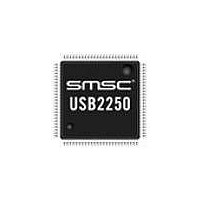
USB2250-NU-05 SMSC, USB2250-NU-05 Datasheet - Page 19

USB2250-NU-05
Manufacturer Part Number
USB2250-NU-05
Description
IC CTRLR USB2.0 FLASH 128VTQFP
Manufacturer
SMSC
Datasheet
1.USB2250-NU-05.pdf
(44 pages)
Specifications of USB2250-NU-05
Controller Type
FlashMedia Controller
Interface
Serial
Voltage - Supply
3 V ~ 3.6 V
Current - Supply
165mA
Operating Temperature
0°C ~ 70°C
Mounting Type
Surface Mount
Package / Case
128-TQFP, 128-VQFP
Operating Supply Voltage
3.3 V
Mounting Style
SMD/SMT
Operating Temperature Range
0 C to + 70 C
Supply Current
80 mA
Lead Free Status / Rohs Status
Lead free / RoHS Compliant
Other names
638-1088
Available stocks
Company
Part Number
Manufacturer
Quantity
Price
Company:
Part Number:
USB2250-NU-05
Manufacturer:
Intersil
Quantity:
171
Company:
Part Number:
USB2250-NU-05
Manufacturer:
Microchip Technology
Quantity:
10 000
Ultra Fast USB 2.0 Multi-Slot Flash Media Controller
Datasheet
SMSC USB2250/50i/51/51i
General Purpose
Input/Output
RESET Input
TEST Input
Regulator
Enable
1.8 V Digital
Core Power
1.8 V PLL Power
3.3 V Power and
Voltage
Regulator Input
Ground
NAME
Note 6.1
Note 6.2
Table 6.1 USB2250/50i/51/51i 128-Pin VTQFP Pin Descriptions (continued)
CRD_PWR2
CRD_PWR3
VDD18PLL
RESET_N
SYMBOL
GPIO10 /
GPIO11 /
REG_EN
VDD18
VDD33
Hot-insertion capable card connectors are required for all flash media. It is required for the
SD connector to have a Write Protect switch. This allows the chip to detect the MMC card.
nMCE is normally asserted except when the 8051 is in standby mode.
TEST
VSS
DIGITAL POWER, and GROUND
128-PIN
VTQFP
103
125
104
128
102
122
126
76
16
64
49
15
50
65
77
17
51
75
81
6
9
DATASHEET
BUFFER
I/O200
I/O200
19
TYPE
I/O12
I/O12
IPU
IS
I
GPIO: This pin may be used either as input,
edge sensitive interrupt input, or output.
Custom firmware is required to activate this
function.
Requirement: This must be the only FET used
to power SM devices. Failure to do this will
violate SM voltage specification on SM device
pins.
CRD_PWR: Card power drive of 3.3 V at
either 100 mA or 200 mA.
GPIO: This pin may be used either as input,
edge sensitive interrupt input, or output.
Custom firmware is required to activate this
function.
CRD_PWR: Card power drive of 3.3 V at
either 100 mA or 200 mA.
This active low signal is used by the system to
reset the chip. The active low pulse should be
at least 1μs wide.
Tie this pin to ground for normal operation.
This signal is used to enable the internal
1.8 V regulator.
If the internal regulator is enabled, then this
pin must have a 1.0
(ESR <0.1 Ω) capacitor to VSS.
If the internal regulator is enabled, then this
pin must have a 1.0
(ESR <0.1 Ω) capacitor to VSS.
If the internal regulator is enabled, pins 50 and
128 each require an external bypass capacitor
of 4.7
Ground Reference
μ
F minimum.
DESCRIPTION
μ
μ
F (or greater) ±20%
F (or greater) ±20%
Revision 2.0 (09-29-09)


