GPM140-30 SL Power, GPM140-30 Datasheet
GPM140-30
Manufacturer Part Number
GPM140-30
Description
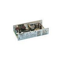
Linear & Switching Power Supplies 140W 100V-240V MED 30V 5.3A 1OUT
Manufacturer
SL Power
Series
GPMr
Datasheet
1.GPM140-30.pdf
(2 pages)
Specifications of GPM140-30
Product
Switching
Commercial/medical
Medical
Output Power Rating
140 W
Input Voltage
100 VAC to 240 VAC
Number Of Outputs
1
Output Voltage (channel 1)
30 V
Output Current (channel 1)
5.3 A
Mounting Style
Chassis
Open Frame/enclosed
Open Frame
Output Type
Single Output


CONDOR DC POWER SUPPLIES INC.
2311 STATHAM PKWY
OXNARD, CA 93033 + 805-486-4565
RATINGS:
Input: 100-240 V ac, 4.0 A, 50/60 Hz
Output:
Notes: 1.
CERTIFICATION: All models are Certified to be in compliance with the applicable requirements of UL 2601-1, CSA 22.2
No. 234 (Level 3) (with additional tests to C22.2 No 601.1-M90 per T.I.L. CA-08), and EN 60601-1: 1990 +A13.
CLASSIFICATION:
GROUNDING: The Protective Earth (ground) terminal J1, pin 5 (TB1-3) must be bonded to Protective Earth in the host
equipment. Using the Protective Earth terminal on the supply for grounding the host equipment is not recommended. A
separate dedicated grounding point should be used.
OUTPUTS: The output common should be connected to Protective Earth in the end application. The output is intended for
Protectively Earthed Signal Output and Intermediate Circuits only. The output is not acceptable for patient connection
without additional isolation. All DC outputs are SELV under normal and single fault conditions.
OVERVOLTAGE PROTECTION: The output is monitored for an overvoltage condition. The trip-point for a 5 volt
output is 5.6 to 6.8 volts. In some applications where an overvoltage condition could result in a hazard as defined in
applicable safety standards, redundant or additional overvoltage protection may be required. Consult factory for details.
CAUTION: When performing Dielectric Strength Tests, catastrophic failure of the unit may result if a Dielectric Strength
test voltage greater than 1800 V ac is applied between primary and secondary circuits. The components providing isolation
from primary to secondary cannot be tested while installed in the power supply without overstressing basic (primary to
ground) insulation. All isolating components are individually 100 % tested at 4800 V ac prior to installation.
41-33340-0001 Rev. E 09/02/04
(In accordance with sub-
clause 5 of EN 60601-1)
GPM140-5
GPM140-12
GPM140-13
GPM140-15
GPM140-24
GPM140-28
GPM140-30
2.
3.
4.
5.
Model
Minimum airflow for forced air cooling is 26 cfm.
Maximum ambient temperature for continuous output power specified above is 50 °C.
I sc = Maximum output short circuit current.
Maximum Relative Humidity 96 %, no condensation.
Storage: -40 to +85 °C. Units should be allowed to warm-up under non-condensing conditions before
application of power.
SAFETY DECLARATION: Condor DC Power Supplies, Inc. declares under our sole responsibility that all
models listed above are in conformity with the applicable requirements of EN 60950 following the provisions
of the Low Voltage Directive 73/23/EEC.
Volts
12
13
15
24
28
30
5
(5.1) Protection against electric shock = Class I
(5.2) Degree of protection against electric shock = Signal output or intermediate
(5.3) Protection against harmful ingress of water = Ordinary (no protection)
(5.5) Has not been evaluated for use in the presence of a flammable anaesthetic mixture with
air, oxygen, or nitrous oxide. This evaluation is made on the end equipment by the OEM.
(5.6) Mode of operation = Continuous
26.0 A 130 W
11.7 A 140 W
10.8 A 140 W
Without Cover
9.3 A 140 W
5.8 A 140 W
5.0 A 140 W
4.7 A 140 W
CONVECTION COOLING
MAXIMUM OUTPUT AMPS AND WATTS
24.0 A 120 W
10.0 A 120 W
9.20 A 120 W
8.0 A 120 W
5.8 A 140 W
5.0 A 140 W
4.7 A 140 W
With Cover
INSTALLATION INSTRUCTIONS
GPM140 SERIES
FORCED AIR COOLING (1)
30.0 A 160 W
13.3 A 160 W
12.3 A 160 W
10.7 A 160 W
6.7 A 160 W
5.7 A 160 W
5.0 A 160 W
With & Without Cover
Page 1 of 2
28.5 A
18.2 A
16.6 A
16.6 A
13.2 A
12.5 A
12.0 A
I sc
Related parts for GPM140-30
Image
Part Number
Description
Manufacturer
Datasheet
Request
R

Part Number:
Description:
Linear & Switching Power Supplies 140W 24V @ 5.8A
Manufacturer:
SL Power
Datasheet:
Part Number:
Description:
Linear & Switching Power Supplies 140W 12V @ 11.7A
Manufacturer:
SL Power
Datasheet:
Part Number:
Description:
Linear & Switching Power Supplies 140W 28V @ 5A
Manufacturer:
SL Power
Datasheet:
Part Number:
Description:
Linear & Switching Power Supplies 140W 15V @ 9.3A
Manufacturer:
SL Power
Datasheet:

Part Number:
Description:
POWER SUP SWITCHER 140W 12V MED
Manufacturer:
SL Power Electronics Manufacture of Condor/Ault Brands
Datasheet:
Part Number:
Description:
POWER SUP SWITCHER 140W 15V MED
Manufacturer:
SL Power Electronics Manufacture of Condor/Ault Brands
Datasheet:
Part Number:
Description:
POWER SUP SWITCHER 140W 24V MED
Manufacturer:
SL Power Electronics Manufacture of Condor/Ault Brands
Datasheet:
Part Number:
Description:
POWER SUP SWITCHER 140W 28V MED
Manufacturer:
SL Power Electronics Manufacture of Condor/Ault Brands
Datasheet:
Part Number:
Description:
Gpm140 Global Performance Switchers
Manufacturer:
SL Power Electronics
Datasheet:
Part Number:
Description:
Linear & Switching Power Supplies 140W 5V @ 26A
Manufacturer:
SL Power
Datasheet:

Part Number:
Description:
50W, 36-75Vin, Single, 2.5V@20A, 1/16 Brick Open Frame, 89% Eff, Pos, SMT, RoHS 6
Manufacturer:
Emerson Network Power
Datasheet:
Part Number:
Description:
System Power Supplies
Manufacturer:
SL Power Electronics
Datasheet:
Part Number:
Description:
Switching Power Supply Modules
Manufacturer:
SL Power Electronics
Datasheet:
Part Number:
Description:
Cent1120 Universal 120 Watt Series
Manufacturer:
SL Power Electronics
Datasheet:
Part Number:
Description:
Gpfc110 Commercial 110 Watt Global Performance Switchers
Manufacturer:
SL Power Electronics
Datasheet:
GPM140-30 Summary of contents
Page 1
... GPM140-12 12 GPM140-13 13 GPM140-15 15 GPM140-24 24 GPM140-28 28 GPM140-30 30 Notes: 1. Minimum airflow for forced air cooling is 26 cfm. 2. Maximum ambient temperature for continuous output power specified above is 50 ° Maximum output short circuit current. 4. Maximum Relative Humidity condensation. 5. Storage: -40 to +85 °C. Units should be allowed to warm-up under non-condensing conditions before application of power ...
Page 2
Secondary to ground creepage is not defined or controlled. The output common is bypassed to ground using capacitor. The required creepage and clearance distances from primary circuits to ground and secondary circuits ...