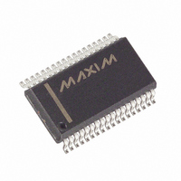
MAX5945EAX+ Maxim Integrated Products, MAX5945EAX+ Datasheet - Page 21

MAX5945EAX+
Manufacturer Part Number
MAX5945EAX+
Description
IC NETWORK PWR CTRL 36-SSOP
Manufacturer
Maxim Integrated Products
Datasheet
1.MAX5945CAX.pdf
(44 pages)
Specifications of MAX5945EAX+
Controller Type
Network Power Controller
Interface
I²C
Voltage - Supply
3.3V
Current - Supply
4.2mA
Operating Temperature
-40°C ~ 85°C
Mounting Type
Surface Mount
Package / Case
36-SSOP
Lead Free Status / RoHS Status
Lead free / RoHS Compliant
Figure 11. Control Byte Received
Figure 12. Control and Single Data Byte Received
Figure 13. ‘n’ Data Bytes Received
A write to the MAX5945 comprises of the MAX5945’s
slave address transmission with the R/W bit set to 0, fol-
lowed by at least one byte of information. The first byte
of information is the command byte (Figure 11). The
command byte determines which register of the
MAX5945 is written to by the next byte, if received. If
the MAX5945 detects a STOP condition after receiving
the command byte, then the MAX5945 takes no further
action beyond storing the command byte. Any bytes
received after the command byte are data bytes. The
first data byte goes into the internal register of the
S
S
Message Format for Writing the MAX5945
HOW CONTROL BYTE AND DATA BYTE MAP
HOW CONTROL BYTE AND DATA BYTE MAP
SLAVE ADDRESS
SLAVE ADDRESS
ACKNOWLEDGE FROM MAX5945
ACKNOWLEDGE FROM MAX5945
CONTROL BYTE IS STORED ON RECEIPT OF STOP CONDITION
______________________________________________________________________________________
S
INTO THE REGISTER
INTO THE REGISTER
R/W
R/W
SLAVE ADDRESS
ACKNOWLEDGE FROM MAX5945
0
0
Quad Network Power Controller
A
A
D15 D14 D13 D12 D11 D10
D15 D14 D13 D12 D11 D10
R/W
CONTROL BYTE
CONTROL BYTE
ACKNOWLEDGE FROM MAX5945
ACKNOWLEDGE FROM MAX5945
0
A
D15
MAX5945 selected by the command byte. If the
MAX5945 transmits multiple data bytes before the
MAX5945 detects a STOP condition, these bytes store
in subsequent MAX5945 internal registers because the
control byte address auto-increments.
Any bytes received after the control byte are data
bytes. The first data byte goes into the internal register
of the MAX5945 selected by the control byte (Figure 8).
If multiple data bytes are transmitted before a STOP
condition is detected, these bytes are stored in subse-
quent MAX5945 internal registers because the control
byte address auto-increments.
D14
D9
D9
D13
for Power-Over-LAN
D8
D8
ACKNOWLEDGE FROM MAX5945
CONTROL BYTE
D12
A
A
D11
D7
D7
D10
D6
D6
D5
D5
D9
ACKNOWLEDGE FROM MAX5945
ACKNOWLEDGE FROM MAX5945
DATA BYTE
DATA BYTE
D4
D4
n BYTES
D8
1 BYTE
D3
D3
A
D2
D2
P
MEMORY WORD ADDRESS
MEMORY WORD ADDRESS
D1
D1
AUTO-INCREMENT
AUTO-INCREMENT
D0
D0
A
A
P
P
21


