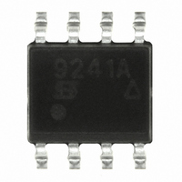
SI9241AEY-T1-E3 Vishay, SI9241AEY-T1-E3 Datasheet - Page 2

SI9241AEY-T1-E3
Manufacturer Part Number
SI9241AEY-T1-E3
Description
IC SINGLE-ENDED BUS TXRX 8-SOIC
Manufacturer
Vishay
Type
Transceiverr
Specifications of SI9241AEY-T1-E3
Logic Type
Single-Ended Bus Transceiver
Number Of Drivers/receivers
1/1
Voltage - Supply
4.5 V ~ 5.5 V
Mounting Type
Surface Mount
Package / Case
8-SOIC (3.9mm Width)
Number Of Channels Per Chip
1
Output Level
CMOS, LSTTL
Output Type
Open Drain
Supply Voltage (max)
36 V
Supply Voltage (min)
6 V
Maximum Operating Temperature
+ 125 C
Minimum Operating Temperature
- 40 C
Mounting Style
SMD/SMT
No. Of Channels
1
Input Level
3.5V
Logic Case Style
SOIC
No. Of Pins
8
Supply Voltage Range
4.5V To 5.5V
Operating Temperature Range
-40°C To +125°C
Lead Free Status / RoHS Status
Lead free / RoHS Compliant
Protocol
-
Lead Free Status / Rohs Status
Lead free / RoHS Compliant
Other names
SI9241AEY-T1-E3TR
Available stocks
Company
Part Number
Manufacturer
Quantity
Price
Company:
Part Number:
SI9241AEY-T1-E3
Manufacturer:
KEMET
Quantity:
1 001
Part Number:
SI9241AEY-T1-E3
Manufacturer:
VISHAY/威世
Quantity:
20 000
AN602
Vishay Siliconix
Since the fault detection signal is not brought out, it is up to the
user to determine if a fault has occurred. One method is to monitor
the RxK and TX lines and ensure they are in phase. An exclusive
OR can also perform the fault function.
The fault condition is cleared when TX is set high.
System Anomalies
Two system anomalies in the automotive environment that the
Si924x drivers may be subjected to are Reverse Battery and
Ground Disconnect.
www.vishay.com
2
RXL
RXK
TX
Battery
Car
FIGURE 3. Si9243A K- and L-Line Driver
V
DD
(See State Diagram
and Truth Table)
V
Logic Circuitry
IN
Processor
Regulator
GND
Micro
GND
V
OUT
V
DD
5 V
RXK
RXL
V
TX
BAT
V
BAT
K
L
+
+
–
–
/2
GND
Logic Circuitry
K
FIGURE 4. Si9243EY Applications Circuit
–
+
V
DD
V
DD
L
K
V
BAT
K
/2
The Si924x drivers have an integrated diode in the V
protect the device from reverse battery conditions. This diode will
protect the IC to reverse batteries up to –24 V.
Signal and Communication Specifications
ISO 9141 specifies different logic levels for the Receiver and
Transmitter.
Receiver Logic Levels:
Transmitter Logic Levels:
The Vishay Siliconix drivers operate to the above specifications,
but with a slightly tighter transmission requirement: Logic “1”
minimum w 0.91*V
A logic bit transition must be less than 10% of the total bit time.
The transition time is measured between the 80% and 20%
battery points. Bit time is defined as the time between the 50%
battery points of consecutive rising and falling levels.
V
Logic “0” v 0.3 * V
0.7 * V
Logic “0” v 0.2 * V
V
BAT
BAT
Si9243
w Logic “1”
BAT
3
Logic “1”
L-Line
K-Line
BAT
.
BAT
BAT
BUS
0.8 *
Diagnostic Tester
V
BAT
510 W
Document Number: 70573
BAT
16-Jan-01
line to


