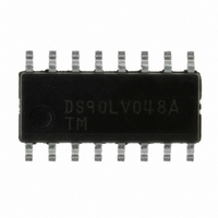
DS90LV048ATM/NOPB National Semiconductor, DS90LV048ATM/NOPB Datasheet - Page 4

DS90LV048ATM/NOPB
Manufacturer Part Number
DS90LV048ATM/NOPB
Description
IC LINE RCVR QUAD CMOS 16-SOIC
Manufacturer
National Semiconductor
Type
Driverr
Datasheet
1.DS90LV048ATMTCNOPB.pdf
(11 pages)
Specifications of DS90LV048ATM/NOPB
Number Of Drivers/receivers
4/0
Protocol
LVDS
Voltage - Supply
3 V ~ 3.6 V
Mounting Type
Surface Mount
Package / Case
16-SOIC (3.9mm Width)
Supply Current
15mA
Supply Voltage Range
3V To 3.6V
Driver Case Style
SOIC
No. Of Pins
16
Operating Temperature Range
-40°C To +85°C
Msl
MSL 1 - Unlimited
Bandwidth
200MHz
Rohs Compliant
Yes
Lead Free Status / RoHS Status
Lead free / RoHS Compliant
Other names
*DS90LV048ATM
*DS90LV048ATM/DRSN
*DS90LV048ATM/NOPB
DS90LV048ATM
DS90LV048ATM/DRSN
DS90LV048ATM/DRSN
*DS90LV048ATM/DRSN
*DS90LV048ATM/NOPB
DS90LV048ATM
DS90LV048ATM/DRSN
DS90LV048ATM/DRSN
Available stocks
Company
Part Number
Manufacturer
Quantity
Price
Company:
Part Number:
DS90LV048ATM/NOPB
Manufacturer:
Maxim
Quantity:
45
Part Number:
DS90LV048ATM/NOPB
Manufacturer:
TI/德州仪器
Quantity:
20 000
www.national.com
Parameter Measurement Information
C
S
S
Typical Application
Applications Information
General application guidelines and hints for LVDS drivers
and receivers may be found in the following application
notes: LVDS Owner’s Manual (lit #550062-002), AN-808,
AN-977, AN-971, AN-916, AN-805, AN-903. The latest appli-
cations
www.national.com/lvds.
LVDS drivers and receivers are intended to be primarily used
in an uncomplicated point-to-point configuration as is shown
L
1
1
= V
= GND for t
includes load and test jig capacitance.
CC
for t
material
PZL
PZH
and t
and t
PLZ
PHZ
is
measurements.
measurements.
available
FIGURE 3. Receiver TRI-STATE Delay Test Circuit
FIGURE 4. Receiver TRI-STATE Delay Waveforms
on
FIGURE 5. Point-to-Point Application
the
web
Balanced System
at:
4
(Continued)
in Figure 5 . This configuration provides a clean signaling
environment for the fast edge rates of the drivers. The re-
ceiver is connected to the driver through a balanced media
which may be a standard twisted pair cable, a parallel pair
cable, or simply PCB traces. Typically, the characteristic
impedance of the media is in the range of 100 . A termina-
tion resistor of 100
located as close to the receiver input pins as possible. The
(selected to match the media), and is
10088805
10088807
10088806


