ES-TN-1H5 BANNER ENGINEERING, ES-TN-1H5 Datasheet - Page 4
ES-TN-1H5
Manufacturer Part Number
ES-TN-1H5
Description
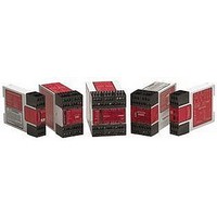
MODULE; SAFETY; E-STOP GUARD; MONITORING MODULE
Manufacturer
BANNER ENGINEERING
Datasheet
1.ES-TN-1H5.pdf
(16 pages)
Specifications of ES-TN-1H5
Coil Voltage Vdc Nom
24V
Contact Current Max
4A
Contact Voltage Ac Nom
250V
Contact Voltage Dc Nom
250V
Contact Configuration
SPST-NC
No. Of Poles
1
Relay Mounting
DIN Rail
External Height
85.5mm


E-Stop Safety Modules with Adjustable Delay
In addition to the safety contacts, the E-Stop Safety Module has one normally closed
immediate auxiliary contact (from K1 and K2) and one normally closed delayed auxiliary
contact (from K3 and K4) for status monitoring by a process controller.
All output contacts of the E-Stop Safety Module, the normally open and the normally
closed, are rated for up to 250V ac/dc at up to 4 amps.
The E-Stop Safety Module also provides a necessary reset function. ANSI B11 and
NFPA 79 standards require that a Reset routine be performed after returning the
E-stop switch to its closed-contact position. This prevents the controlled machinery
from restarting simply by closing the E-stop switch. Models ES-TN-1H5 and -1H6 may
be configured for Automatic Reset via two DIP switches located inside the Module
housing, under the front cover (see Figures 5 and 6). Automatic Reset mode is
useful for some automated processes. However, when Automatic Reset is used,
an alternate means must be established to require a Reset routine after the E-stop
switch is returned to its closed-contact position (see WARNING on page 9).
This E-stop Safety Module complies with the following design standards:
EN418
EN954-1
EN292-2–1991
IEC 60204-1–1997 Safety of Machinery: Electrical Equipment of Machines
The Safety Module has indicators for input power (Power), internal faults (Fault), E-
stop inputs (E-Stop), reset input (Reset), monitoring of feedback contacts (Monitor),
immediate outputs (Out) and delayed outputs (Timed-Out); see Figure 1.
E-Stop Safety Modules ES-TN-1H5 and -1H6 have no user-serviceable parts. See page
16 for information regarding repair service.
4
P/N 58697 rev. A
Emergency Stop Equipment - Functional Aspects,
Principles for Design
Safety of Machinery: Safety-related Parts of Control Systems
Part 1: General Design Directives (Safety Category 4)
Safety of Machinery: Basic Concepts, General Principles for Design
Part 2: Technical Principles and Specifications
Part 1: General Requirements
— Models ES-TN-1H5/-1H6
Banner Engineering Corp.
www.bannerengineering.com • Tel: 763.544.3164
Figure 1. ES-TN-1H5 and -1H6 status
indicators
POWER
FAULT
E-STOP
RESET
MONITOR
OUT
TIMED
OUT
•
K1 & K2
Minneapolis, MN U.S.A.
X1
37 38 61 62
A1
X5 X6
X2 13 14
S11
S12
51 52 23 24
47 48 Y1 Y2
S21 S22 A2
X3 X4
K3 & K4
TIMED
Related parts for ES-TN-1H5
Image
Part Number
Description
Manufacturer
Datasheet
Request
R

Part Number:
Description:
ES-TN-1H1 ES FIXED DELAY .250 DELAYED OUTPUT
Manufacturer:
BANNER ENGINEERING
Part Number:
Description:
ES-TN-14H5-71694 IMED/DELAYED
Manufacturer:
BANNER ENGINEERING

Part Number:
Description:
Sensor, E-stop Module, output 6A,
Manufacturer:
BANNER ENGINEERING
Datasheet:

Part Number:
Description:
Photoelectric Sensor
Manufacturer:
BANNER ENGINEERING
Datasheet:

Part Number:
Description:
Programmable Indicator Light
Manufacturer:
BANNER ENGINEERING
Datasheet:
Part Number:
Description:
INDICATOR LED PANEL 50MM GRN/RED/YEL 30V
Manufacturer:
BANNER ENGINEERING
Datasheet: