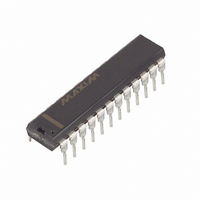
MAX238CNG+ Maxim Integrated Products, MAX238CNG+ Datasheet - Page 11

MAX238CNG+
Manufacturer Part Number
MAX238CNG+
Description
IC 4DVR/4RCVR RS232 5V 24-DIP
Manufacturer
Maxim Integrated Products
Type
Transceiverr
Datasheet
1.MAX222CPN.pdf
(38 pages)
Specifications of MAX238CNG+
Number Of Drivers/receivers
4/4
Protocol
RS232
Voltage - Supply
4.5 V ~ 5.5 V
Mounting Type
Through Hole
Package / Case
24-DIP (0.300", 7.62mm)
Package
24PDIP N
Data Transmission Topology
Point-to-Point
Interface Standards
EIA/TIA-232-E|RS-232|V.24|V.28
Data Rate
0.12 Mbps
Function
Line Transmitter/Receiver
Number Of Transmitters
4
Transmitter Signal Type
Single-Ended
Transmitter Communication Type
RS-232
Typical Single Supply Voltage
5 V
Supply Voltage (max)
5.5 V
Supply Voltage (min)
4.5 V
Maximum Operating Temperature
+ 70 C
Mounting Style
Through Hole
Interface
RS-232
Maximum Power Dissipation
500 mW
Minimum Operating Temperature
0 C
Supply Current
7 mA
Lead Free Status / RoHS Status
Lead free / RoHS Compliant
Figure 1. Transmitter Propagation-Delay Timing
Figure 3. Receiver-Output Enable and Disable Timing
INPUT
OUTPUT
b) ENABLE TIMING
c) DISABLE TIMING
a) TEST CIRCUIT
t
PLHT
+3V
RECEIVER
RECEIVER
EN INPUT
OUTPUTS
EN INPUT
OUTPUTS
R
X
V
V
EN
OH
IN
OL
______________________________________________________________________________________
+3V
0V
R
X
R
X
0V
OUT
150pF
+3V
0V
1kΩ
+5V-Powered, Multichannel RS-232
OUTPUT DISABLE TIME (t
OUTPUT ENABLE TIME (t
V
V
+3.5V
+0.8V
OH
OL
+ 0.5V
- 0.5V
EN
EN
V
V
CC
CC
- 2V
- 2V
t
PHLT
ER
DR
V+
0V
V-
)
)
Figure 2. Receiver Propagation-Delay Timing
Figure 4. Transmitter-Output Disable Timing
OUTPUT
*EXCEPT FOR R2 ON THE MAX243
INPUT
WHERE -3V IS USED.
t
t
PHLR
PHLS
Test Circuits/Timing Diagrams
SHDN
1 OR 0
b) TEST CIRCUIT
a) TIMING DIAGRAM
V+
V-
0V*
Drivers/Receivers
+3V
T
X
50%
50%
+3V
0V
3kΩ
+5V
-5V
OUTPUT DISABLE TIME (t
50pF
0V
50%
50%
GND
t
t
DT
PLHR
PLHS
)
V
CC
11


