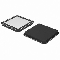
AMIS-49250-XTD ON Semiconductor, AMIS-49250-XTD Datasheet - Page 15

AMIS-49250-XTD
Manufacturer Part Number
AMIS-49250-XTD
Description
IC TXRX FIELDBUS MAU 44-NQFP
Manufacturer
ON Semiconductor
Type
Transceiverr
Datasheet
1.AMIS-49200-XTD.pdf
(22 pages)
Specifications of AMIS-49250-XTD
Number Of Drivers/receivers
1/1
Protocol
MDS-MAU
Voltage - Supply
4.75 V ~ 6.2 V
Mounting Type
Surface Mount
Package / Case
44-LQFP
Logic Type
Fieldbus Media Access Unit
Logic Family
AMIS-492x0
Number Of Channels Per Chip
1
Input Level
CMOS
Output Level
CMOS
Output Type
Open Drain
High Level Output Current
50 uA
Low Level Output Current
50 uA
Supply Voltage (max)
6.2 V
Supply Voltage (min)
3 V
Maximum Operating Temperature
+ 85 C
Minimum Operating Temperature
- 40 C
Mounting Style
SMD/SMT
Polarity
Inverting/Non-Inverting
Number Of Transmitters
1
Power Supply Requirement
Dual
Operating Temperature Classification
Industrial
Mounting
Surface Mount
Pin Count
44
Operating Temperature (max)
85C
Operating Temperature (min)
-40C
Lead Free Status / RoHS Status
Lead free / RoHS Compliant
Other names
AMIS-49250-XTDOS
Available stocks
Company
Part Number
Manufacturer
Quantity
Price
Company:
Part Number:
AMIS-49250-XTD
Manufacturer:
ON Semiconductor
Quantity:
10 000
AMIS-492x0
4.3.3. Slew Rate Controller
Amplifier (A3), shown in the above figure, controls the slew rate. The amplifier converts the current signals from the tri-level modulator
to a voltage signal, VDRV. It controls its slew rate with a capacitor (C
symmetric and the fall/rise times are determined by the following equation:
The constant part comes from the internal capacitor (not shown). It is recommended to make a guard pattern on your circuit board
around the CRT pin and the hot side of C
4.3.4. Current Drive Amplifier
The drive amplifier is an operational amplifier optimized to drive current drivers for 31.25kbps voltage-mode medium. Its input and
output signals are exposed to allow flexible design of the external driver. Note that this amplifier cannot directly sink the necessary
current from the medium. In the following drive circuit the current (I
following equation.
A diode and/or a resistor connected to the emitter are necessary to shift the DC level of CCOUT and to suppress the loop gain. The
resistance value depends on your design (overall gain and emitter current).
N_VL
N_Vs
400K
20R
RT
I
bus
to avoid unnecessary interference.
=
Tri-Level Modulator
Active Low
t
80K
Rev. 6 | Page 15 of 22 | www.onsemi.com
4R
F
Slew Control
, t
R
[ R
Figure 9: Tri-level Modulator
= 2.0[μs] + 0.12 [μs/pF] × C
&
3
Active Low
V
mid
VMID
80K
4R
(R
- [ R
12
+ R
F
BUS
RT
( R
11
) connected to the CRT pin. The waveform at the VDRV pin is
) through the current-detect resister (R
) ] - [ V
2
VCC
R
20K
A3
R
12
+ R
drv
(R
3
RT
R
2
12
R
) ]
11
+ R
3
R
11
VDRV
CRT
) ]
1.2K
1.2K
1.2K
21
19
F
) is determined by the


