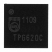
ISP1109BSFE ST-Ericsson Inc, ISP1109BSFE Datasheet - Page 24

ISP1109BSFE
Manufacturer Part Number
ISP1109BSFE
Description
IC TXRX SERIAL BUS UNIV 32HVQFN
Manufacturer
ST-Ericsson Inc
Type
Transceiverr
Datasheet
1.ISP1109BSFE.pdf
(60 pages)
Specifications of ISP1109BSFE
Number Of Drivers/receivers
1/1
Protocol
USB 2.0
Voltage - Supply
3 V ~ 5.25 V
Mounting Type
Surface Mount
Package / Case
32-VQFN Exposed Pad, 32-HVQFN, 32-SQFN, 32-DHVQFN
Lead Free Status / RoHS Status
Lead free / RoHS Compliant
Other names
568-3148
ISP1109BS
ISP1109BS
Available stocks
Company
Part Number
Manufacturer
Quantity
Price
Company:
Part Number:
ISP1109BSFE
Manufacturer:
ST-EricssonInc
Quantity:
1 143
Philips Semiconductors
Table 25:
Table 27:
9397 750 13355
Product data sheet
Bit
Symbol
Reset
Access
Bit
Symbol
Reset
Access
Timer Control register (address Set = 18h, Clear = 19h) bit allocation
Resistor Control register (address Set = 06h, Clear = 07h) bit allocation
9.1.2.4 Timer Control register (S/C: 18h/19h)
9.1.2.5 Resistor Control register
VBUS_
CHRG
R/S/C
R/S/C
7
0
7
0
Table 24:
The bit allocation of the Timer Control register is given in
Table 26:
Table 27
Bit
4
3
2
1
0
Bit
7 to 4
3 to 0
DISCHRG
VBUS_
R/S/C
R/S/C
6
0
6
0
TMR_SE1[3:0]
shows the bit allocation of the Resistor Control register.
Symbol
ISET_STATE
ISET_DRV_EN
SW_MIC_
SPKR_R
SW_MIC_
SPKR_L
AUDIO_MONO
Symbol
TMR_SE1[3:0]
-
Audio Control register (address Set = 16h, Clear = 17h) bit description
Timer Control register (address Set = 18h, Clear = 19h) bit description
reserved
R/S/C
R/S/C
5
0
5
0
Rev. 01 — 14 July 2005
Description
Determines the logic level for pin ISET when bit ISET_DRV_EN is
logic 1.
0 — ISET outputs LOW
1 — ISET outputs HIGH.
Enables software control of the state of pin ISET:
0 — Disable; the ISET output will be controlled by hardware
1 — Enable; the ISET output will be controlled by bit ISET_STATE.
Audio loopback test:
0 — Turn off the switch between the MIC and SPKR_R pins
1 — Turn on the switch between the MIC and SPKR_R pins.
Audio loopback test:
0 — Turn off the switch between the MIC and SPKR_L pins
1 — Turn on the switch between the MIC and SPKR_L pins.
Selection between stereo and mono audio modes:
0 — Stereo mode: SPKR_L
1 — Mono mode: SPKR_L
Description
Program the timer value to detect SE1 on the DP and DM lines. The
interval is 1 ms (Default value = 1 ms).
reserved
ID_PULL
R/S/C
R/S/C
DN
4
1
4
0
DM_PULL
DOWN
R/S/C
R/S/C
3
0
3
0
USB transceiver with carkit support
DM, MIC
DM, SPKR_R
DP_PULL
DOWN
R/S/C
R/S/C
Table
2
0
2
0
© Koninklijke Philips Electronics N.V. 2005. All rights reserved.
reserved
25.
DP.
DP_WKPU
R/S/C
R/S/C
_EN
DP
1
0
1
1
ISP1109
…continued
DP_PULL
R/S/C
R/S/C
UP
0
0
0
1
23 of 59


