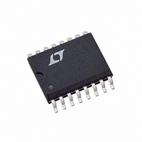
LTC1520CS#TR Linear Technology, LTC1520CS#TR Datasheet - Page 3

LTC1520CS#TR
Manufacturer Part Number
LTC1520CS#TR
Description
IC LINE RCVR RS485 QUAD 16SOIC
Manufacturer
Linear Technology
Type
Line Receiverr
Datasheet
1.LTC1520CSPBF.pdf
(8 pages)
Specifications of LTC1520CS#TR
Number Of Drivers/receivers
0/4
Protocol
LVDS
Voltage - Supply
4.75 V ~ 5.25 V
Mounting Type
Surface Mount
Package / Case
16-SOIC (3.9mm Width)
Lead Free Status / RoHS Status
Contains lead / RoHS non-compliant
Available stocks
Company
Part Number
Manufacturer
Quantity
Price
TYPICAL PERFORMANCE CHARACTERISTICS
SWITCHI G TI E CHARACTERISTICS
V
SYMBOL
t
t
t
t
t
t
t
t
f
The
temperature range.
Note 1: Absolute Maximum Ratings are those values beyond which the
safety of the device cannot be guaranteed. Recommended: V
Note 2: All currents into the device pins are positive; all currents out of the
device pins are negative.
PLH
r
SKD
ZL
ZH
LZ
HZ
CH-CH
t
IN
, t
PKG-PKG
DD
f
, t
25
20
15
10
= 5V 5% (Notes 2, 3) V
5
0
PHL
denotes specifications which apply over the full operating
–50 –25
Propagation Delay (t
vs Temperature
V
V
CM
ID
PARAMETER
Input-to-Output Propagation Delay
Rise/Fall Times
Enable to Output Low
Enable to Output High
Disable from Output Low
Disable from Output High
Channel-to-Channel Skew
Package-to-Package Skew
Minimum Input Pulse Width
Maximum Input Frequency
= 500mV
= 2.5V
t
PLH
U
– t
0
TEMPERATURE ( C)
PHL
25
Skew
W
50
PLH
ID
75
/t
= 500mV, V
W
PHL
100
LTC1520 G01
)
U
125
CM
= 2.5V, unless otherwise noted.
25
20
15
10
5
0
0.05
CONDITIONS
C
C
C
C
C
C
C
C
C
(Figure 4, Note 4)
(Note 4)
(Note 4)
L
L
L
L
L
L
L
L
L
Propagation Delay (t
vs Input Overdrive
DD
= 15pF (Figure 1)
= 15pF
= 15pF, Same Receiver (Note 5)
= 15pF (Figure 2)
= 15pF (Figure 2)
= 15pF (Figure 2)
= 15pF (Figure 2)
= 15pF (Figure 3) (Note 6)
= 15pF, Same Temperature
= 5V 5%.
0.1
INPUT OVERDRIVE (V)
Note 3: All typicals are given for V
Note 4: Guaranteed by design, but not tested.
Note 5: Worst-case t
over the full operating temperature range.
Note 6: Maximum difference between any two t
single package over the full operating temperature range.
1
PLH
/t
T
V
PHL
A
CM
= 25 C
= 2.5V
)
5
1520 G02
10
PLH
– t
PHL
MIN
20
15
10
25
15
5
0
0
skew for a single receiver in a package
DD
Propagation Delay (t
vs Input Common Mode
T
V
A
ID
= 5V, T
= 25 C
= 500mV
1
INPUT COMMON MODE (V)
TYP
500
400
2.5
1.5
18
10
10
20
20
12
40
A
= 25 C.
PLH
2
or t
LTC1520
MAX
PHL
21
35
35
35
35
3
PLH
transitions in a
/t
PHL
4
LTC1520 G03
)
UNITS
3
MHz
ns
ns
ps
ns
ns
ns
ns
ps
ns
ns
5


