NJM2624AM-TE1 NJR, NJM2624AM-TE1 Datasheet
NJM2624AM-TE1
Specifications of NJM2624AM-TE1
Available stocks


Related parts for NJM2624AM-TE1


NJM2624AM-TE1 Summary of contents
Page 1
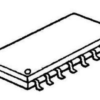
... Bipolar Technology Package Outline PIN CONFIGRATION =4.5V to 18V) (10mA max.) (90mA typ.) DIP16, DMP16, SSOP16 PIN FUNCTION 16 15 1.H1- 14 2.H1+ 13 3.H2+ 4.H2- 12 5.H3- 11 6.H3 8.V NJM2624A PACHAGE OUTLINE NJM2624AD NJM2624AM NJM2624AV 9.GND 10.ON/OFF 11.OUT1 12.OUT3 13.OUT5 14.OUT6 15.OUT4 16.OUT2 Ver 1.0 3 ...
Page 2
NJM2624A BLOCK DIAGRAM H1+ 2 H1- 1 H2+ 3 H2- 4 H3+ 6 H3- 5 ABSOLUTE MAXIMUM RATINGS (Ta=25°C) PARAMETER Supply Voltage Output Current Power Dissipation Operating Temperature Range Storage Temperature Range - 2 - Forward or Reverse 7 Hall ...
Page 3
ELECTRICAL CHARACTERISTICS (V Total Device PARAMETER SYMBOL Supply Voltage V Supply Current I Hall Sensor Section Input Offset Voltage V Input Common mode V Voltage range Input Bias Current I Output Section Output Voltage 1 V OUT1 Output Voltage 2 ...
Page 4
NJM2624A TERMINAL DESCRIPTION Pin SYMBOL FUNCTION No, 2 H1+ Sensor Input 1 Non-Inverting Terminal 3 H2+ Sensor Input 2 Non-Inverting Terminal 6 H3+ Sensor Input 3 Non-Inverting Terminal 1 H1- Sensor Input 1 Inverting Terminal 4 H2- Sensor Input 2 ...
Page 5
TERMINAL DESCRIPTION Pin SYMBOL FUNCTION No Power Supply 9 GND Ground 10 ON/OFF Output Run Enable Terminal 11 OUT1 Internal Switching Transistor 16 OUT2 Emitter Follower 12 OUT3 15 OUT4 13 OUT5 14 OUT6 INSIDE EQUIVALENT CIRCUIT ...
Page 6
NJM2624A TYPICAL APPLICATION • A rotation direction change must be made after motor stopped completely. • When PWM duty is extremely small, two or more switching elements can not be driven entirely. In such case, switching elements will generate excess ...
Page 7
TIPICAL CHARACTERISTICS Supply Current vs. Supply Voltage (Ta=25° Supply Voltage V Input Bias Current vs. Supply Voltage + (Input=1/2V ,Ta=25° Supply ...
Page 8
NJM2624A TIPICAL CHARACTERISTICS Maximum Output Current vs.Temperature + (V =12V,RL=100Ω) 110 105 100 95 90 -50 -25 0 Ambient Temperature Ta (°C) Output Leak Current vs.Temperature + (V =12V,RL=0Ω 0.1 0.01 0.001 -50 - Ambient Temperature ...