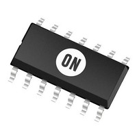
UC3842AD ON Semiconductor, UC3842AD Datasheet - Page 13

UC3842AD
Manufacturer Part Number
UC3842AD
Description
Other Power Management 52kHz 1A Current PWM
Manufacturer
ON Semiconductor
Type
High Performance Current Mode Controllersr
Datasheet
1.UC3843AN2.pdf
(18 pages)
Specifications of UC3842AD
Output Voltage Range
4.9 V to 5.1 V
Input Voltage Range
30 V
Operating Temperature Range
0 C to + 70 C
Mounting Style
SMD/SMT
Package / Case
SOIC-14
Lead Free Status / Rohs Status
Lead free / RoHS Compliant
Available stocks
Company
Part Number
Manufacturer
Quantity
Price
Company:
Part Number:
UC3842AD
Manufacturer:
MOT
Quantity:
2 435
Company:
Part Number:
UC3842AD1
Manufacturer:
MAXIM
Quantity:
2 341
Company:
Part Number:
UC3842AD2R2G
Manufacturer:
ST
Quantity:
18 388
Company:
Part Number:
UC3842AD8
Manufacturer:
TI
Quantity:
13 817
Part Number:
UC3842AD8
Manufacturer:
TI/德州仪器
Quantity:
20 000
Company:
Part Number:
UC3842AD8TR
Manufacturer:
ON
Quantity:
10 000
Part Number:
UC3842AD8TR
Manufacturer:
TI/德州仪器
Quantity:
20 000
Part Number:
UC3842ADR2G
Manufacturer:
ON/安森美
Quantity:
20 000
Figure 27. Current Waveform Spike Suppression
The totem−pole output can furnish negative base current for enhanced
transistor turn−off, with the addition of capacitor C
The addition of the RC filter will eliminate instability caused by the leading
edge spike on the current waveform.
The MCR101 SCR must be selected for a holding of less than 0.5 mA at T
The simple two transistor circuit can be used in place of the SCR as shown. All
resistors are 10 k.
Figure 29. Bipolar Transistor Drive
MCR
101
−
+
5.0V
+
0
−
−
+
+
−
ref
I
B
Comp/Latch
Figure 31. Latched Shutdown
3905
S
R
2N
Q
6(1)
5(8)
3(5)
+
−
Removal
+
Charge
7(12)
−
Base
3903
2N
8(14)
4(7)
2(3)
1(1)
C
1
V
CC
7(11)
6(10)
5(8)
3(5)
1
UC3842A, UC3843A, UC2842A, UC2843A
.
+
−
Q1
R
EA
V
R
R
S
in
C
+
R
Osc
1.0mA
Bias
Q1
R
V
2R
S
in
R
A(min)
5(9)
.
http://onsemi.com
−
+
5.0V
13
−
+
+
−
ref
Comp/Latch
S
R
Q
Error Amp compensation circuit for stabilizing current−mode boost and flyback
topologies operating with continuous inductor current.
Error Amp compensation circuit for stabilizing any current−mode topology except
for boost and flyback converters operating with continuous inductor current.
Series gate resistor R
caused by the MOSFET input capacitance and any series wiring inductance
in the gate−source circuit.
+
−
Figure 30. Isolated MOSFET Drive
C
Figure 28. MOSFET Parasitic Oscillations
Figure 32. Error Amplifier Compensation
R
p
From V
+
7(12)
−
R
p
From V
R
d
i
−
+
R
O
C
5.0V
R
O
i
I
V
d
7(11)
6(1)
5(8)
3(5)
−
+
CC
+
−
ref
C
Comp/Latch
g
C
I
R
will damp any high frequency parasitic oscillations
S
R
2(3)
1(1)
f
Q
Boundary
Isolation
R
R
R
S
2(3)
1(1)
+
f
−
2.5V
+
−
+
7(12)
−
N
EA
2.5V
S
+
+
−
Q1
1.0mA
EA
V
CC
7(11)
6(10)
5(8)
3(5)
+
N
V
+
0
2R
p
−
I
pk
in
É É É
1.0mA
R
50% DC
=
R
2R
g
É
V
V
5(9)
(pin 1)
R
GS
3 R
Waveforms
− 1.4
5(9)
S
Q1
+
0
R
−
V
S
in
É É É É
25% DC
N
N
P
S


