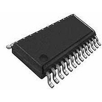
CS5467-IS Cirrus Logic Inc, CS5467-IS Datasheet - Page 14

CS5467-IS
Manufacturer Part Number
CS5467-IS
Description
Other Power Management 4-Ch Single Phase Power/Energy IC
Manufacturer
Cirrus Logic Inc
Datasheet
1.CS5467-ISZ.pdf
(46 pages)
Specifications of CS5467-IS
Mounting Style
SMD/SMT
Package / Case
SSOP-28
Lead Free Status / Rohs Status
Lead free / RoHS Compliant
Available stocks
Company
Part Number
Manufacturer
Quantity
Price
Part Number:
CS5467-ISZ
Manufacturer:
CIRRUSLOGIC
Quantity:
20 000
4. SIGNAL PATH DESCRIPTION
The data flow for voltage and current measurement and
the other calculations are shown in Figures 3, 4, and 5.
4.1 Analog-to-Digital Converters
Voltage1 channel and voltage2/temperature channel
use second-order delta-sigma modulators and the two
current channels use fourth-order delta-sigma modula-
tors to convert the analog inputs to single-bit digital data
streams. The converters sample at a rate of DCLK/8.
This high sampling provides a wide dynamic range and
simplifies anti-alias filter design.
4.2 Decimation Filters
The single-bit modulator output data is widened to 24
bits and down-sampled to DCLK/1024 with low-pass
decimation filters. These decimation filters are third-or-
der Sinc. Their outputs are passed through third-order
14
FGA
FGA
1
2
2
Figure 3. Signal Flow for V1, I1, P1, Q1 Measurements
Figure 4. Signal Flow for V2, I2, P2, Q2 Measurements
Control Register
V1
V2
I1
I2
VHPF1 IHPF1
OFF
OFF
VHPF2 IHPF2
OFF
OFF
IIR “anti-sinc” filters, used to compensate for the ampli-
tude roll-off of the decimation filters.
4.3 Phase Compensation
Phase compensation changes the phase of current rel-
ative to voltage by changing the sampling time in the
decimation filters. The amount of phase shift is set by
bits PC[7:0] in the Configuration register ( Config ) for
channel 1 and bits PC[7:0] in the Control register ( Ctrl )
for channel 2.
Phase compensation, PC[7:0] is a signed two’s comple-
ment binary value in the range of -1.0 to almost +1.0
output word rate (OWR) samples. For a sample rate of
4000 Hz, the delay range is ±250 uS, a phase shift of
±4.5° at 50 Hz and ±5.4° at 60 Hz. The step size would
be 0.0352° at 50 Hz and 0.0422° at 60 Hz at this sample
rate.
V1
V2
I1
I2
GAIN
GAIN
GAIN
GAIN
V2
I2
P2
CS5467
DS714F1
V2Q
Q2


