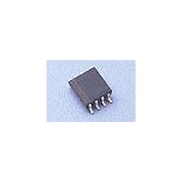
CAT813TZI-GT3 Catalyst / ON Semiconductor, CAT813TZI-GT3 Datasheet - Page 8

CAT813TZI-GT3
Manufacturer Part Number
CAT813TZI-GT3
Description
Supervisory Circuits 4.65V Active-High
Manufacturer
Catalyst / ON Semiconductor
Datasheet
1.CAT813TVI-GT3.pdf
(14 pages)
Specifications of CAT813TZI-GT3
Number Of Voltages Monitored
1
Monitored Voltage
3 V, 3.6 V, 5 V
Manual Reset
Resettable
Watchdog
Watchdog
Supply Voltage (max)
5.5 V
Supply Voltage (min)
1.2 V
Supply Current (typ)
17 uA
Maximum Power Dissipation
330 mW
Maximum Operating Temperature
+ 85 C
Mounting Style
SMD/SMT
Package / Case
MSOP-8
Minimum Operating Temperature
- 40 C
Lead Free Status / Rohs Status
Lead free / RoHS Compliant
CAT705, CAT706, CAT813
WATCHDOG TIMER
The CAT705,
Watchdog input (WDI). The watchdog timer function
controls the watchdog output (WDO
the WDO
not have a transition from low-to-high or high-to-low
within 1.6s typical. If a transition occurs on the WDI
input pin prior to the watchdog time-out, the watchdog
timer is restarted. The timing diagram is shown in
Figure 3. The watchdog timer starts as soon as reset
condition becomes inactive.
When the V
the WDO
independently of the watchdog timing stage.
Figure 4 below shows a typical implementation of a
watchdog function. Any processor signal that repeats
dependant on the normal operation of the processor
Doc. No. MD-3030 Rev. E
¯¯¯¯ to be low (active) when the WDI input does
¯¯¯¯ output becomes active and goes low
CC
supply drops below the reset threshold,
(RESET)
CAT706,
RESET
WDO
WDI
GND
V
MR
PFI
+5 V
+5 V
+5 V
+5 V
CC
0 V
0 V
0 V
0 V
(() Are for CAT813 Only)
&
CAT705
CAT706
CAT813
¯¯¯¯ ) signal and forces
t WP
CAT813
Figure 3. Watchdog Timing Diagram
Figure 4. Watchdog Timer Circuit
WDO
RESET/RESET
WDI
PFO
t WD
provide a
RESET EXTERNALLY
TRIGGERED BY MR
MCLR
8
or directed by the software operating on the processor
can be used to strobe the watchdog input. The most
reliable is a dedicated I/O output transitioned by a
specific software instruction.
The watchdog can be disabled by floating (or tri-
stating) the WDI input (see Figure 5). If the watchdog
is disabled the WDI pin will be pulled low for the first
7/8
the last 1/8
of the WDI input and then high is used to detect an
open or tri-state condition and will continue to repeat
until the WDI input is driven high or low.
For most efficient operation of devices with the
watchdog function the WDI input should be held low
the majority of the time and only strobed high as
required to reset the watchdog timer.
PIC
µC
th
t WD
’s of the watchdog period (t
ADDRESS
th
of the watchdog period. This pulling low
DECODER
t RS
t WD
Characteristics subject to change without notice
WD
© 2010 SCILLC. All rights reserved.
) and pulled high for


