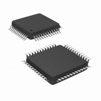
DP83848CVV/NOPB National Semiconductor, DP83848CVV/NOPB Datasheet - Page 13

DP83848CVV/NOPB
Manufacturer Part Number
DP83848CVV/NOPB
Description
IC TXRX ETHERNET PHYTER 48-LQFP
Manufacturer
National Semiconductor
Type
Transceiverr
Datasheet
1.DP83848CVVXNOPB.pdf
(84 pages)
Specifications of DP83848CVV/NOPB
Number Of Drivers/receivers
1/1
Protocol
Ethernet
Voltage - Supply
3 V ~ 3.6 V
Mounting Type
Surface Mount
Package / Case
48-LQFP
For Use With
DP83848C-POE-EK - BOARD EVALUATION DP83848CDP83848C-MAU-EK - BOARD EVALUATION DP83848C
Lead Free Status / RoHS Status
Lead free / RoHS Compliant
Other names
*DP83848CVV
*DP83848CVV/NOPB
DP83848CVV
DP83848CVVNOPB
DP83848CVVNOPB
DP83848CVVNOPBTR
DP83848CVVNOPBTR
*DP83848CVV/NOPB
DP83848CVV
DP83848CVVNOPB
DP83848CVVNOPB
DP83848CVVNOPBTR
DP83848CVVNOPBTR
Available stocks
Company
Part Number
Manufacturer
Quantity
Price
Company:
Part Number:
DP83848CVV/NOPB
Manufacturer:
TI
Quantity:
7 600
Company:
Part Number:
DP83848CVV/NOPB
Manufacturer:
NS
Quantity:
4 021
Company:
Part Number:
DP83848CVV/NOPB
Manufacturer:
Texas Instruments
Quantity:
10 000
Part Number:
DP83848CVV/NOPB
Manufacturer:
TI/德州仪器
Quantity:
20 000
AN_EN (LED_ACT/COL)
AN_1 (LED_SPEED)
AN_0 (LED_LINK)
MII_MODE (RX_DV)
SNI_MODE (TXD_3)
LED_CFG (CRS)
MDIX_EN (RX_ER)
Signal Name
S, O, PU
S, O, PD
S, O, PU
S, O, PU
Type
Pin #
26
27
28
39
40
41
6
Auto-Negotiation Enable: When high, this enables Auto-Negoti-
ation with the capability set by ANO and AN1 pins. When low, this
puts the part into Forced Mode with the capability set by AN0 and
AN1 pins.
AN0 / AN1: These input pins control the forced or advertised op-
erating mode of the DP83848C according to the following table.
The value on these pins is set by connecting the input pins to
GND (0) or V
NEVER be connected directly to GND or VCC.
The value set at this input is latched into the DP83848C at Hard-
ware-Reset.
The float/pull-down status of these pins are latched into the Basic
Mode Control Register and the Auto_Negotiation Advertisement
Register during Hardware-Reset.
The default is 111 since these pins have internal pull-ups.
MII MODE SELECT: This strapping option pair determines the
operating mode of the MAC Data Interface. Default operation (No
pull-ups) will enable normal MII Mode of operation. Strapping
MII_MODE high will cause the device to be in RMII or SNI mode
of operation, determined by the status of the SNI_MODE strap.
Since the pins include internal pull-downs, the default values are
0.
The following table details the configurations:
LED CONFIGURATION: This strapping option determines the
mode of operation of the LED pins. Default is Mode 1. Mode 1 and
Mode 2 can be controlled via the strap option. All modes are con-
figurable via register access.
SeeTable 3 for LED Mode Selection.
MDIX ENABLE: Default is to enable MDIX. This strapping option
disables Auto-MDIX. An external pull-down will disable Auto-
MDIX mode.
13
AN_EN AN1
AN_EN AN1
MII_MODE
0
0
0
0
1
1
1
1
CC
(1) through 2.2 k resistors. These pins should
0
1
1
0
0
1
1
0
0
1
1
SNI_MODE
Description
AN0
AN0
0
1
0
1
0
1
0
1
X
0
1
10BASE-T, Half-Duplex
10BASE-T, Full-Duplex
100BASE-TX, Half-Duplex
100BASE-TX, Full-Duplex
10BASE-T, Half/Full-Duplex
100BASE-TX, Half/Full-Duplex
10BASE-T Half-Duplex
100BASE-TX, Half-Duplex
10BASE-T, Half/Full-Duplex
100BASE-TX, Half/Full-Duplex
Advertised Mode
MII Mode
RMII Mode
10 Mb SNI Mode
Forced Mode
MAC Interface
Mode
www.national.com


